Optical Crosstalk in CMOS Image Sensors
Chris Fesenmaier and Benjamin Sheahan
Psych 221 - Winter 2006-2007
| Welcome | ||
| Introduction | ||
| Methods | ||
| Pixel Scaling | ||
| Methods | ||
| Results | ||
| Conclusions | ||
| References | ||
| Crosstalk Reduction | ||
| Methods | ||
| Air Gaps | ||
| Light Guide | ||
| Metal Mirrors | ||
| Results | ||
| Reference | ||
| Air Gaps | ||
| Light Guide | ||
| Metal Mirrors | ||
| Conclusions | ||
| References | ||
| Appendices | ||
Results - Light Guide
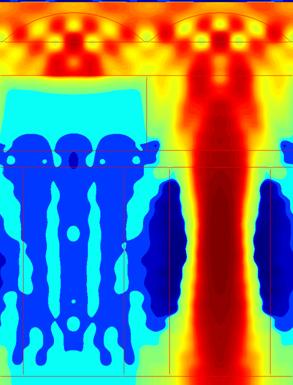
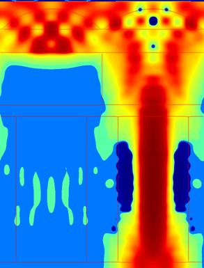
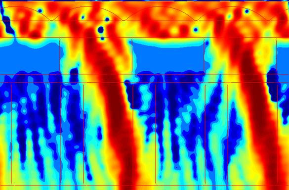
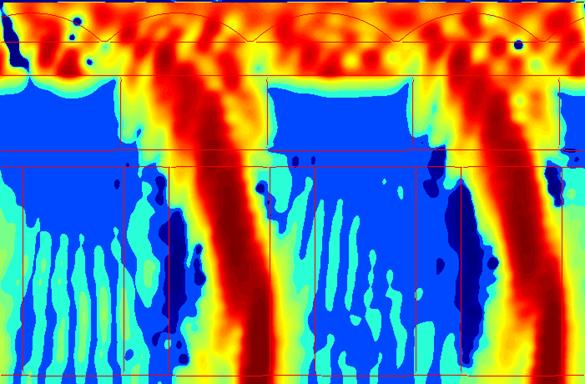
The light guide designs show similar tradeoffs as the air gap designs. At normal incidence, both suppress the crosstalk, but the n = 1.8 design transmits less light because its higher refractive index causes increased reflection, which was verified in the simulations. For off-axis incidence, however, the higher-index light guide confines the light much more effectively, leading to vastly higher transmission and lower crosstalk. The improved optical confinement can be seen in the Poynting vector plots by generally lower values outside of the light guide of the target pixel.
|
|
(a) |
(b) |
Fig. 13. Poynting vector plots for the n = 1.6 light guide (a) and n = 1.8 light guide (b) designs for normal incidence. |
|
|
Fig. 13. Poynting vector plot for the n = 1.6 light guide design at 25° incidence. |
|
Fig. 14. Poynting vector plot for the n = 1.8 light guide design at 25° incidence. |
|
(a) |
|
(b) |
Fig. 15. Transmission (a) and crosstalk (b) versus incident angle for the two light guide and reference pixels. |