Optical Crosstalk in CMOS Image Sensors
Chris Fesenmaier and Benjamin Sheahan
Psych 221 - Winter 2006-2007
| Welcome | ||
| Introduction | ||
| Methods | ||
| Pixel Scaling | ||
| Methods | ||
| Results | ||
| Conclusions | ||
| References | ||
| Crosstalk Reduction | ||
| Methods | ||
| Air Gaps | ||
| Light Guide | ||
| Metal Mirrors | ||
| Results | ||
| Reference | ||
| Air Gaps | ||
| Light Guide | ||
| Metal Mirrors | ||
| Conclusions | ||
| References | ||
| Appendices | ||
Methods - Light Guide
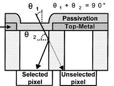
The light guide method operates on a principle very similar to the air gap method. Instead of creating a low-index area between the pixels, the refractive index of the pixel center material is increased. This technique has been recently explored [7] by the same group at TSMC with some success, although the limited index contrast achieved (1.02) would only cause TIR for angles less than about 10°.
|
|
(a) |
(b) |
Fig. 6. Illustrations describing the benefits of TIR (a), where light is prevented from leaving the intended pixel, and refraction (b), where the lateral travel of non-reflected light is reduced, for the light guide method. Courtesy Hsu et al. [7]. |
|
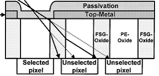
This structure is formed by simply etching away the material over the active pixel area and depositing a higher-index transparent material. The main difficulty here is that the replacement material must satisfy several requirements. First, it must be optically transparent, otherwise it will absorb light and the sensor light sensitivity will decrease. Second, it must be electrically and mechanically compatible with the other materials. Finally, it must have a refractive index high enough to promote TIR of a sufficient range of angles. It is also important to consider that a change in refractive index of the light tunnel material will affect the optical properties of the pixel even for perfectly normal incidence.
Simulations were performed using two light guide materials with refractive indices of 1.6 and 1.8, corresponding to critical angles of 24.1° and 35.8°. These represent cases where there is significant index contrast and no absorption. The width of the light guide is equal to the width of the active pixel area (1.2 µm).