Optical Crosstalk in CMOS Image Sensors
Chris Fesenmaier and Benjamin Sheahan
Psych 221 - Winter 2006-2007
| Welcome | ||
| Introduction | ||
| Methods | ||
| Pixel Scaling | ||
| Methods | ||
| Results | ||
| Conclusions | ||
| References | ||
| Crosstalk Reduction | ||
| Methods | ||
| Air Gaps | ||
| Light Guide | ||
| Metal Mirrors | ||
| Results | ||
| Reference | ||
| Air Gaps | ||
| Light Guide | ||
| Metal Mirrors | ||
| Conclusions | ||
| References | ||
| Appendices | ||
Results - Air Gaps
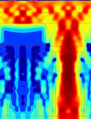
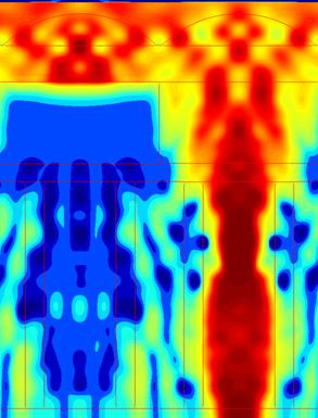
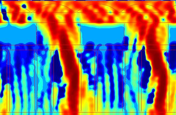
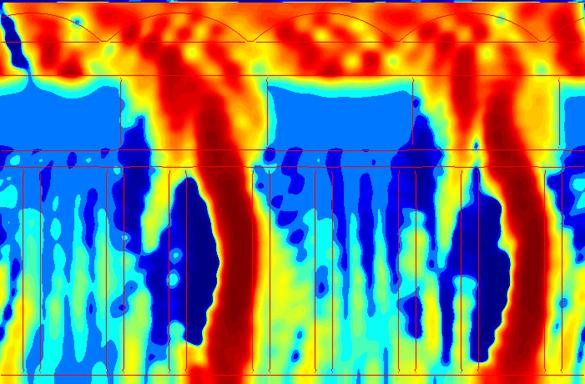
The air gap results demonstrate a strong dependence on the thickness of the gap. For the 0.1 µm void, there is a significant amount of coupling to the other side of the gap. In the 0.2 µm case, there is less coupling, but the increased width of the gaps allows a smaller aperture for the light to enter. The latter effect dominates at normal incidence, where the thinner voids have a higher transmission and lower crosstalk. At an angle, however, the coupling through the gap is enhanced, leading to declining transmission and increasing crosstalk. As Figures 11 and 12 show, the wider air gap is able to confine the light more efficiently and therefore performs better for off-axis incidence.
|
|
(a) |
(b) |
Fig. 10. Poynting vector plots for the 0.1 µm air gap (a) and 0.2 µm air gap (b) designs for normal incidence. |
|
|
Fig. 11. Poynting vector plot for the 0.1 µm air gap design at 25° incidence. |
|
Fig. 12. Poynting vector plot for the 0.2 µm air gap design at 25° incidence. |
|
(a) |
|
(b) |
Fig. 12. Transmission (a) and crosstalk (b) versus incident angle for the two air gap and reference pixels. |