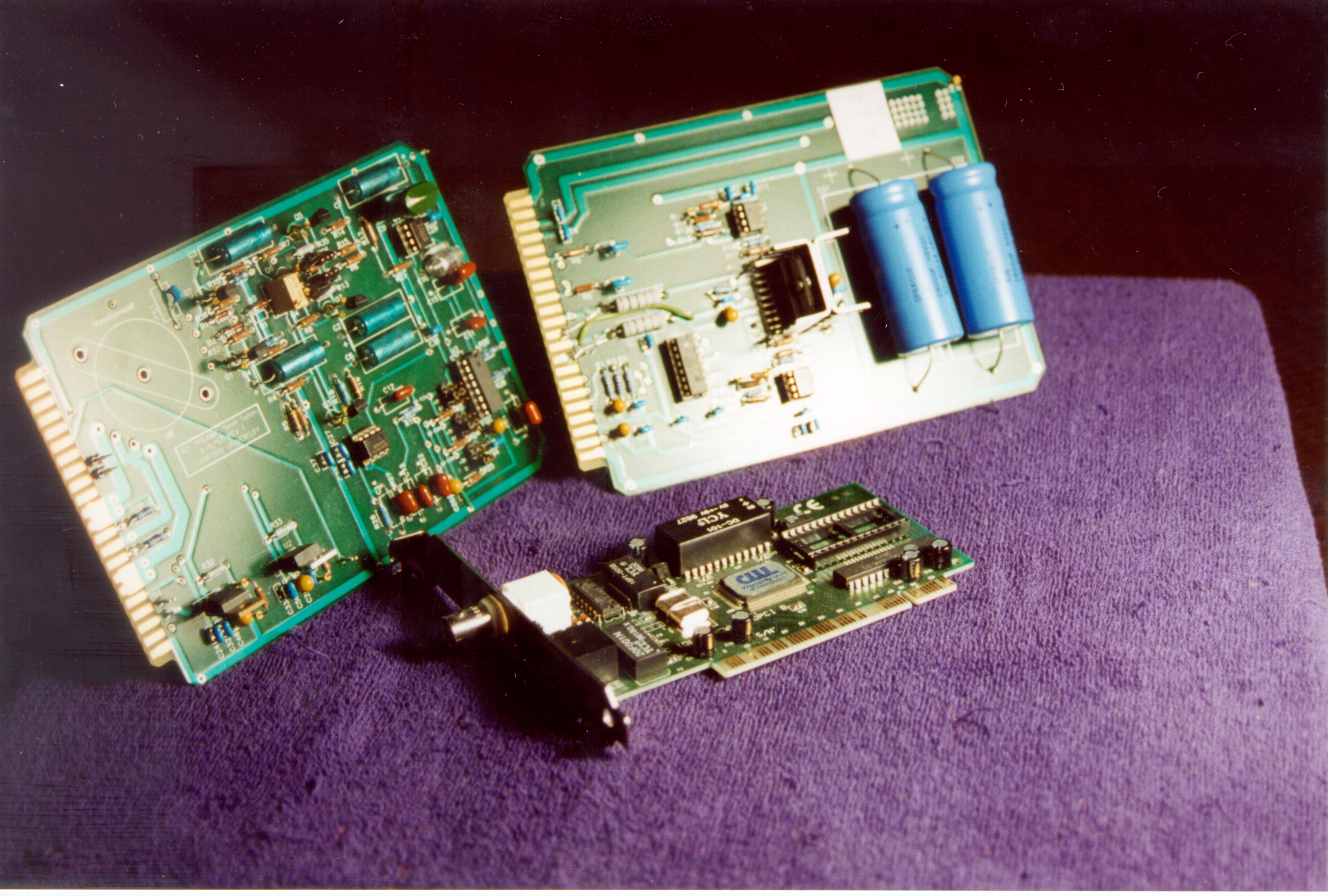
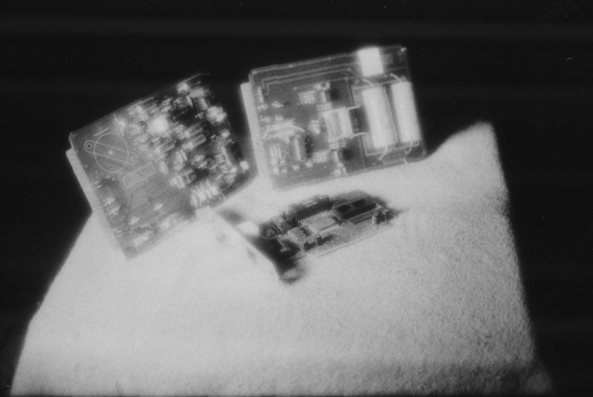
The circuits were chosen for their plethora of materials. Two preamplifier cards for VLF signal acquisition, dubbed the left and right circuitboards below, are shown standing. Laying on the table is an old network card. All materials, however, proved to be metallic and thus very reflective, even in the near infrared. Thus, the majority of the pictures were very similar with and without the filter, regardless of light source.
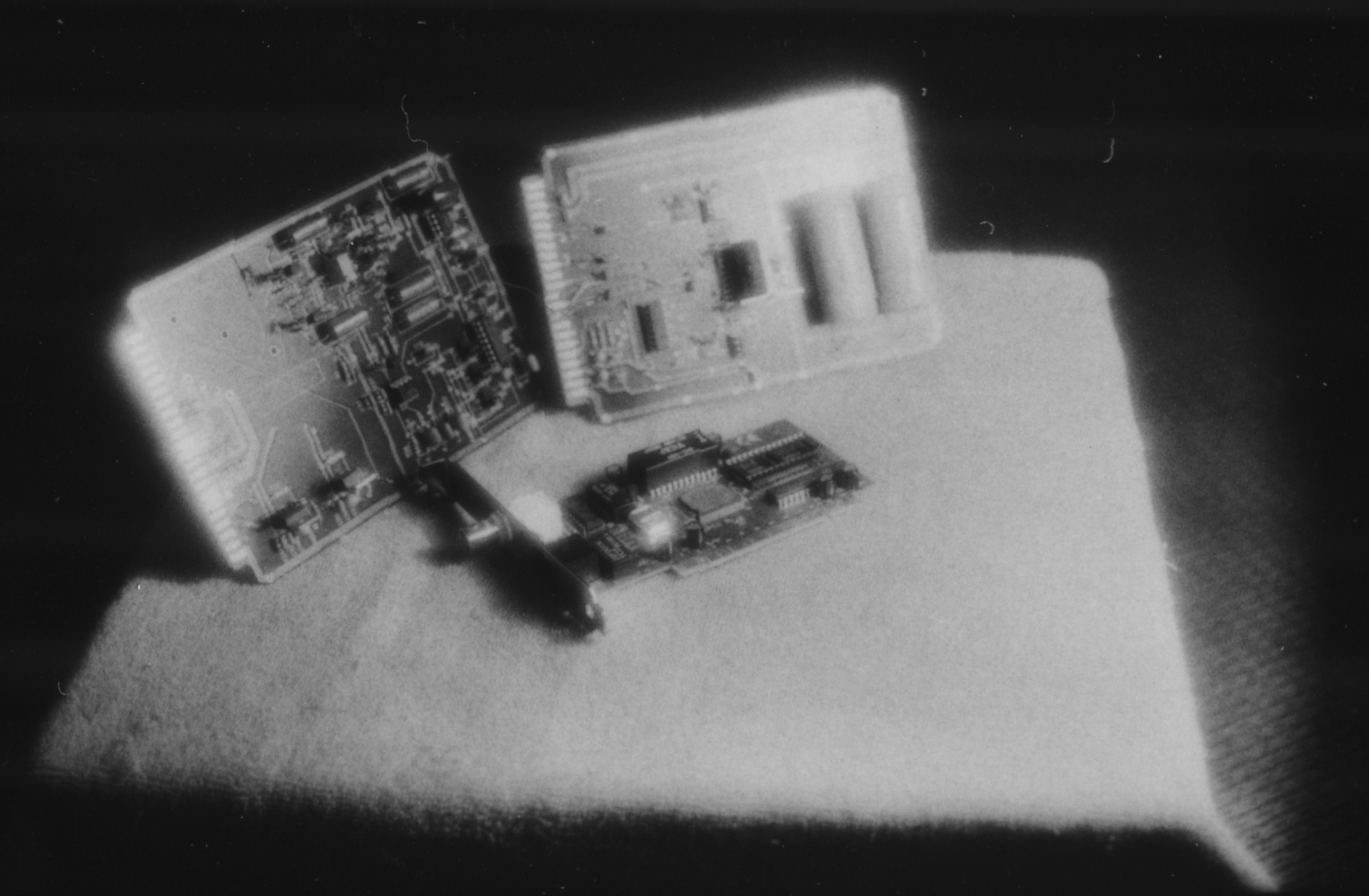
In both cases, the high reflectance of the blue metallic capacitors and red plastic coating of the smaller ceramic capacitors in the left circuitboard dominate the image. Deviations in color make little difference - this can be seen by comparing the above mentioned blue and red capacitors in any of the pictures below. Instead, the key differentiator of color is simply darkness or lightness of hue - compare the flat blue capacitors with the dark green upright capacitor in the upper right of the left circuitboard - a standard characteristic expected of black and white film in general. In fact, to characterize the pictures as simply measuring brightness, as would be done by standard black and white film, appears an accurate statement regardless of filter or light source.
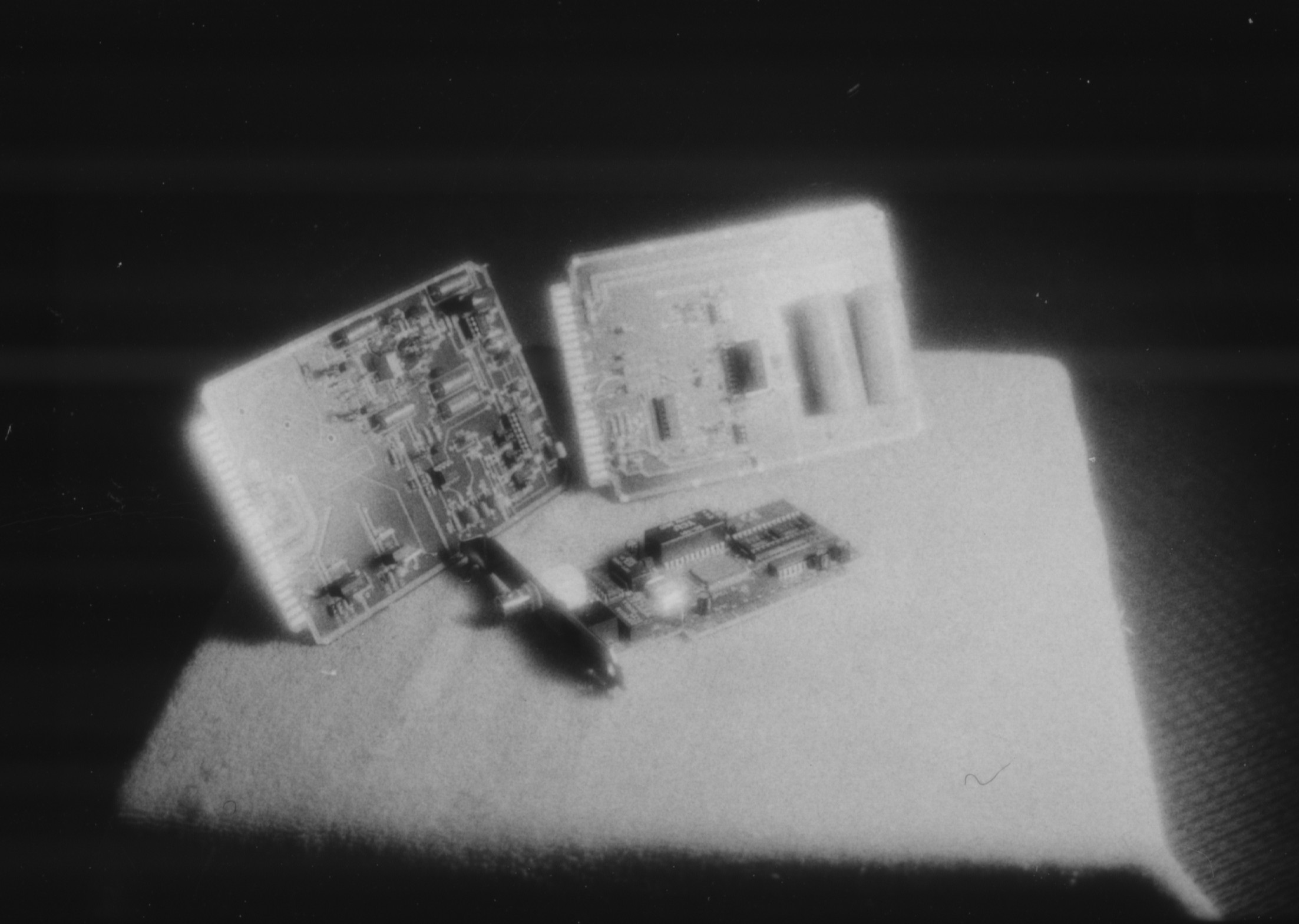
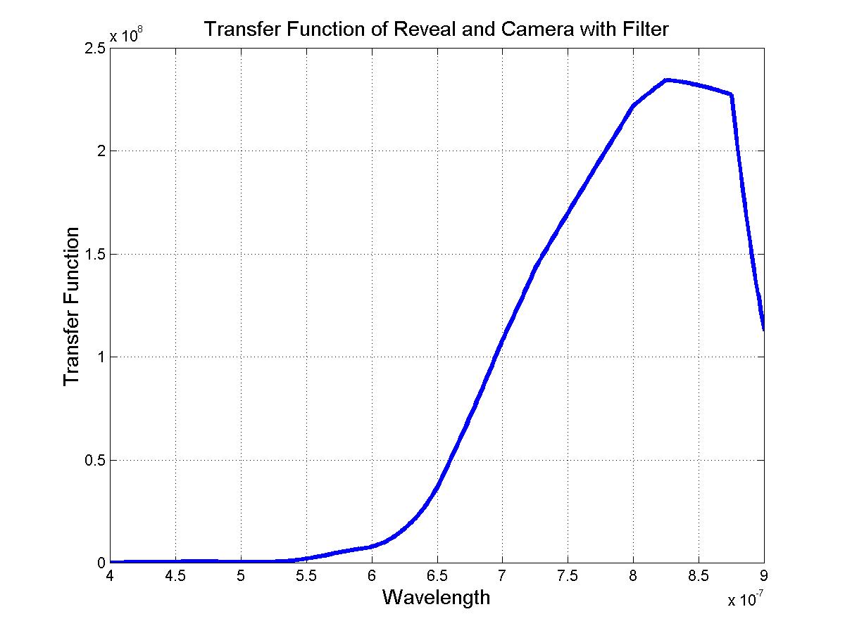
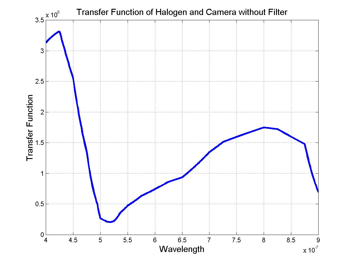
It is also notable that the increased infrared brightness of the Reveal bulb over the Halogen bulb results in a net increase in image brightness.
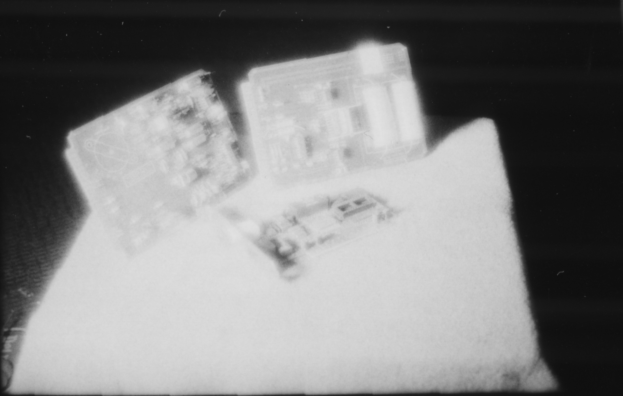
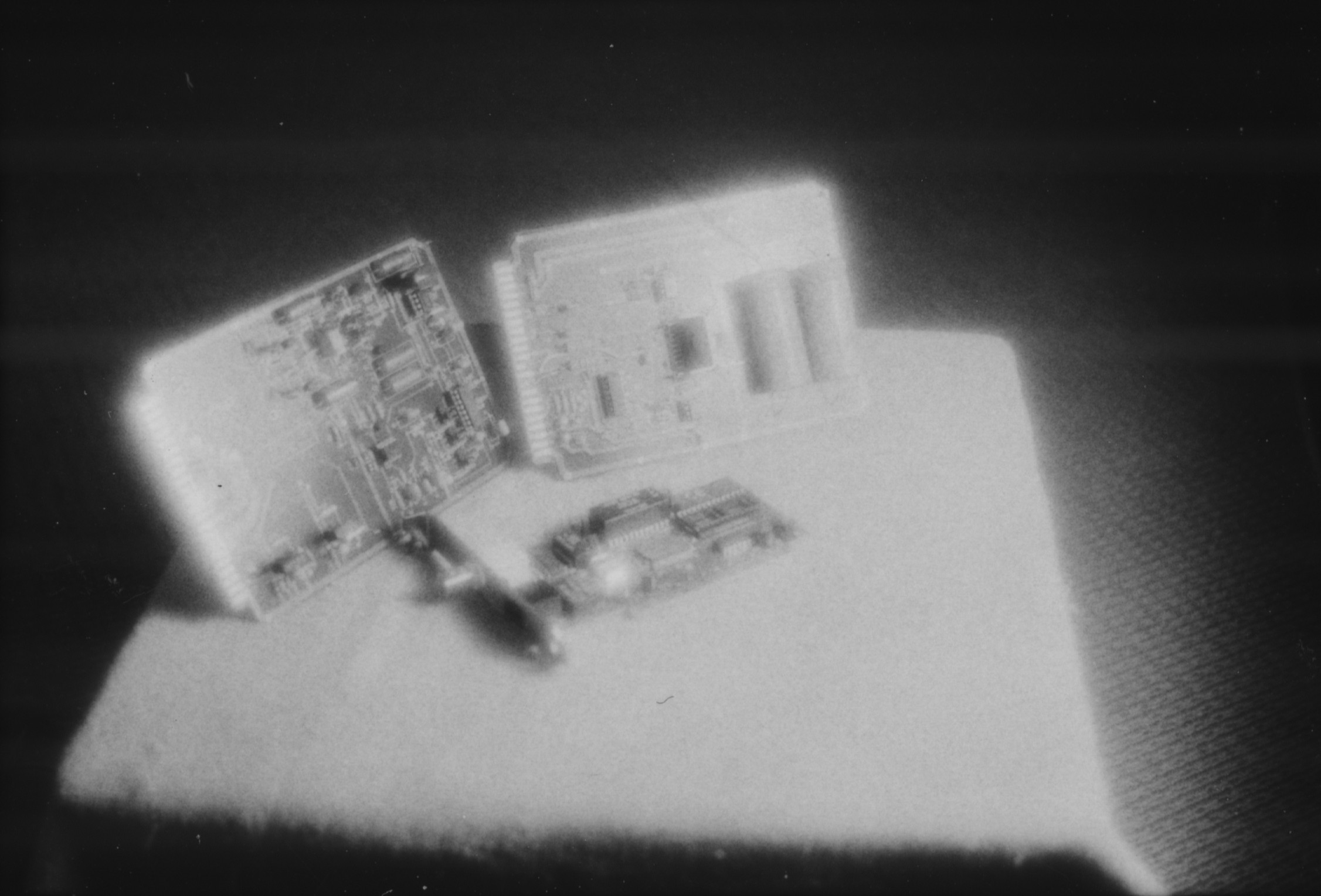
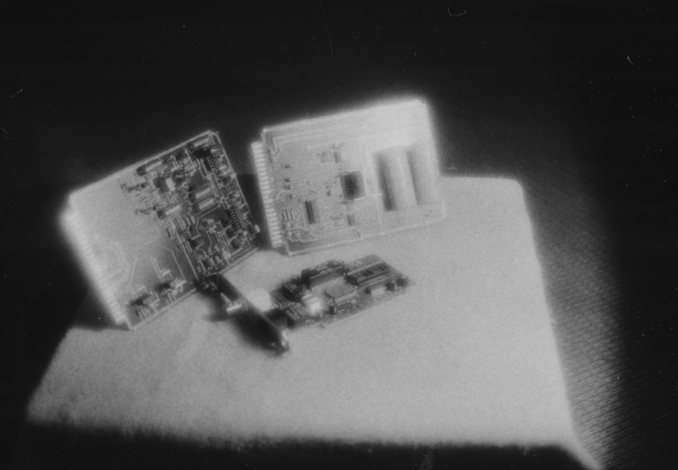
The filtered strobe light image shown below is interesting insofar as the illumination comes from the left and slightly behind the left circuitboard. Note that the traces of the left circuitboard appear as dark against a light background, whereas the traces of the right circuitboard appear light on dark. This is probably because the image of the left circuitboard image is transmission light dominated, whereas the right circuitboard is reflection light dominated. This can also seen in the inverted translucence of the two blue metallic caps in the center of the left circuitboard.
Home Introduction Applications Methodology Modeling Results Conclusion References Appendix I Appendix II