Home | Introduction | Background | Schemes | Conclusion | References | Appendix
Foveated Video Broadcast
The Scenario
A simple video broadcast scenario is depicted in Figure 5. A central server streams the same video content to several geographically-distributed viewers. Each viewer is, of course, free to fixate on any point of the screen and free to change that fixation during the streaming. We suppose the transmission apparatus to be a beamforming antenna array, in order to preclude viewers sharing data streams.
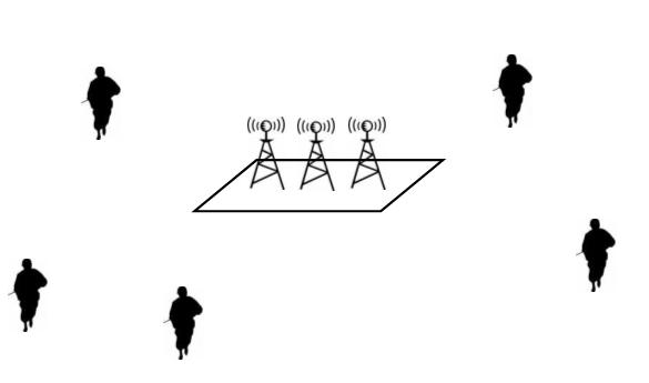
Figure 5: Video broadcast scenario
Scheme I: No Foveation
The server streams identical unfoveated video to all viewers. Each viewer is, thus, free to trace an arbitrary gaze trajectory. The advantage of this strategy is that the encoder needs to keep track of only a single decoder state since all decoders produce the same output. However, this scheme fails to exploit the gains in compression possible under foveation. Hence, required receiver bandwidth suffers.
Scheme II: Individual Foveation
The server applies a foveated video strategy (as in [2]) for each viewer independently. In this way, required receiver bandwidth can be reduced. On the other hand, the encoder needs to maintain separate decoder states for each viewer and encode video frames separately with respect to each of them. So, in this scheme, encoder complexity scales with the number of viewers.
Scheme III: Joint Foveation Coding
At each frame instant, the server sends the same coded foveated video frame to all viewers who have the same current point of fixation; viewers with difference gaze directions receive different coded frame information. The encoding is done in such a way that a frame can be decoded regardless of the decoder's state, which depends on the viewer's gaze trajectory up to that time. Hence, the encoder need not keep track of all decoder states; instead, its complexity scales only with the number of different points of fixation. At the same time, the receivers benefit from a reduction in required bandwidth due to foveation. The precise mechanism is described after an illustrative example.
Figure 6 depicts the operation of a joint foveation coding system. First, observe that the encoder transmits common motion information to all viewers since, as far as motion is concerned, they all view the same content. Now, we consider each viewer in turn. The viewer on the left has traced a certain gaze trajectory, which creates a particular decoder state signified by the blue looping arrow. The blue arrow from the encoder denotes the present coded frame corresponding to the left viewer's current point of fixation. The viewer on the right is in a similar situation, except for having traced a different gaze trajectory and having a different current fixation. The viewer in the middle shares the same decoder state as the viewer on the left as a result of having the same prior gaze trajectory. However, at the current frame instant, the middle viewer fixates at the same point as the viewer on the right. Under this scheme, the encoder can simply send the middle viewer the same coded frame that it transmits to the right viewer.
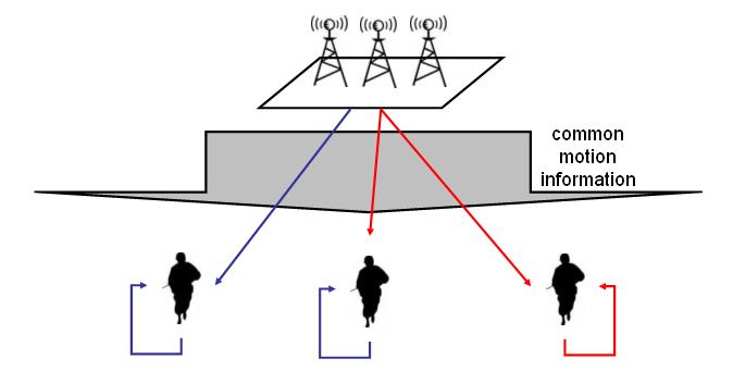
Figure 6: Joint foveation coding
The theoretical premise of this strategy was established in by Wyner and Ziv [3] in 1976. A comprehensive review of Wyner-Ziv coding along with several video applications is presented in [4]. Along these lines, we propose the system architecture shown in Figure 7, for joint foveation coding.
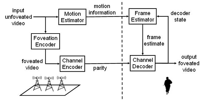
Figure 7: System architecture
At the encoder, motion information is extracted from the unfoveated video input and transmitted to the viewer. This branch of the encoder is common for all transmissions to viewers. The other encoder branch is only common for viewers who have the same current gaze direction. In this branch, each video frames is foveated and then channel coded to produce a stream of parity bits, which is also transmitted.
At the decoder, the received motion information is combined with the decoder state to generate a frame estimate. Then, a channel decoder uses the received parity bits to 'correct errors' in the frame estimate relative to the encoder's foveated frame. In this way, it produces a faithful output foveated video frame. Finally, the output frame feeds back into the frame estimator as the new decoder state. Observe that the operation of the decoder does not require the encoder to know the decoder state precisely. This is the key to the encoder complexity savings under joint foveation coding.
Simulation
For each of the foveated video broadcast schemes described above, we computed the conditional entropy rate of the frame transmission for the Bus video sequence. Since the conditional entropy rate is the lower bound for lossless transmission, these values were added to the rate for transmission of motion information to yield estimates of required receiver bandwidth. Table 1 compares the receiver bandwidth measurements as well as asymptotic encoder complexities. These results demonstrate that joint foveation coding is more successful at trading-off required receiver bandwidth and encoder complexity than naďve individual foveation.
| Required Receiver Bandwidth (MB/sec) | Encoder Complexity | |
| Scheme I | ||
| Scheme II | ||
| Scheme III |
Table 1: Performance of foveated video broadcast schemes