Psych 221: Applied Vision and Imaging Systems
Multispectral Illuminator
By: Max Klein, Winter 2008
Introduction and Motivation
Multispectral imaging provides more information about objects than what the human eye can resolve, since our eyes only have three types of cones. For example, our eyes cannot see any ultraviolet or infrared. Traditional imagers use three distinct spectral bins for sampling an image, namely a red, green, and blue. The resulting data from these imagers can reproduce an image roughly as the human eye perceives it, however much information about the actual wavelength-by-wavelength spectra of each point is lost. Images with more than just 3 spectral bins of information are referred to as multispectral or hyperspectral images. These images can provide significant scientific information about a scene, and are often used in medicine for blood, skin, and other diagnostics, as well as in the industrial and military arenas for terrain mapping and material composition determination, to name a few.
Multispectral imaging can be performed in two primary methods: a broadband source and narrow band detectors or narrow band sources and broadband detectors. Narrow band detectors for more than 3 wavelengths are not readily available, however narrow band light sources are. Thus, for this class we will be building a multispectral illuminator for use with a traditional grayscale or RGB imager.
Existing LED-based light sources, such as those by Color Kinetics (now Philips), typically have only three separate illuminators near red, green, and blue. These devices have a large gamut relative to what the human eye can see and are able to reproduce a majority of the colors that we can see. They are not, however, able to provide illumination that would assist in determining the absolute reflectance spectrum of an object any better than a white light and RGB-filtered color camera can provide.
The SCIEN Lab already has a multispectral illuminator setup, consisting of a tungsten lamp plus several filters/gels that can be switched in to determine the band of light being emitted. This setup has a very high intensity due to the theater-style light being used, however it is extremely slow to change gels manually. Due to the time lag in between shots of different wavelength illumination, this setup is prohibitively slow for live scenes.
Requirements
- Multiple narrow-band spectral channels
- 6+ wavelengths required
- Independently controllable
- Pulse Width Modulation desirable, not necessary for imaging
- Must use inexpensive COTS LEDs and components
- 1W Luxeon LumiLEDs within budget
- Metal core PCBs not within budget
- Higher intensity is better
- Should be maximized based on available components
- Fast (~100ms or better) switching time between channels
- Prevents registration blur between images
- Illumination time of up to 30sec may be necessary
- Photometric readings, etc
- Camera Control / Coordination
- Lighting unit should be computer controlled to allow integration with dSLR controller software
- Alternatively, lighting unit can directly control camera
- Shutter speed, aperture control, etc not available with this option
Component Selection and System Design
The most important component in the design are the LEDs themselves. The LEDs used were picked with extensive consultation with Joyce Farrell and Manu Parmar. We settled on the Luxeon 1W LEDs for 5 visible colors (Royal Blue, Cyan, Green, Amber, Red), plus one "UV" LED which is actually a deeper blue at 430nm, and two infrared LEDs at 880nm and 940nm. The Royal Blue LEDs were doubled on the board due to their expected lower output power, which proved to be incorrect as discussed in the Future Work section.
Between these 8 unique LEDs present on the board, there are 4 different forward voltages, and thus likely four different current limiting circuits. Since LEDs are current-based devices, we decided to use a LM317 voltage regulator in current regulation mode for each strand of LEDs by placing a sense resistor between the output and adjust terminals of the device and supplying the LEDs from the output of the resistor at the adjust pin. This circuit requires approximately 3V of headroom on the input rail.
From these constraints, a supply voltage was selected. The more LEDs that can be placed in series, the fewer current regulators will be necessary, but also the higher the system voltage. In an attempt to use a "standard" voltage to make finding a COTS power supply more easy, we settled on a 15VDC supply, which had enough voltage to supply at least three LEDs in series, and yet is readily available in a small, switching power supply often used for laptop computers. Assuming that at most two channels of LEDs will be illuminated at once, a 4A supply is necessary.
To supply switch the power to the LM317 regulators, a N-channel MOSFET (IRF7470) was selected that well exceeded the current requirement of 4A and yet is available at low cost in a small package. Since the MOSFET will be primarily on or off, heat generation should be extremely small except possibly during PWM operation.
The brain of the system needs to have at least 9 PWM channels to control the MOSFETs, as well as a UART to communicate with a PC as well as two GPIO lines for triggering the camera. An Atmel AVR ATmega1280 / 2560 microcontroller is appropriate for this use with 12 PWM channels, two USARTS, and plenty of GPIO and memory for the application. Two GPIO lines are used to drive an optoisolator (LTV8141) for camera focus and shutter triggering. Four GPIO lines are used for status LED indicators, and 9 PWM lines are used for MOSFET control. To support chaining of multiple lighting units, the RS232 receive line is passed through to the slave output port, allowing a message sent from the PC to be received by multiple lighting units simultaneously. This is a simple method to chain units, however bidirectional communication with the slave units is not possible (nor necessary).
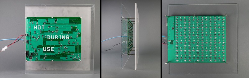
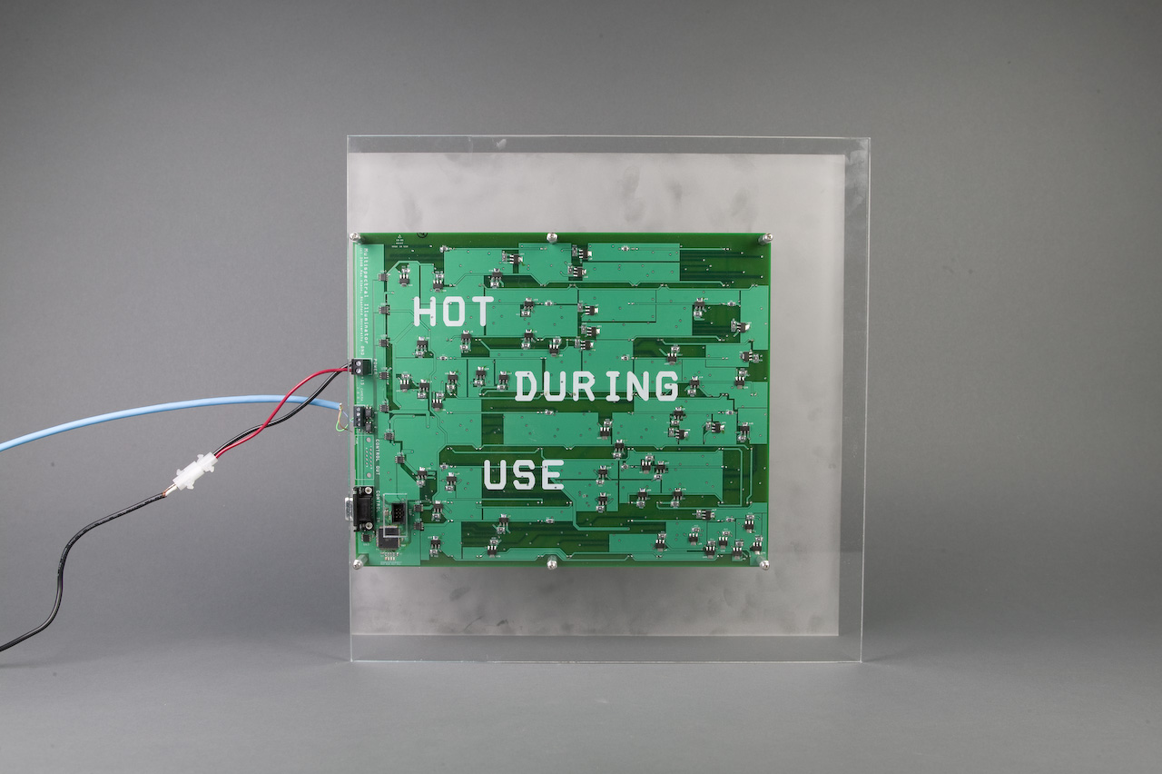
One important consideration during the layout of the PCB is heat. The Luxeon LEDs have a center stud that is attached to the die (and thus not electrically isolated) that must be connected to a heat sink. With metal core PCBs outside of the budget for our project, we opted to minimize traces on the top layer of the board and instead create a large copper pour to be used as a heat sink. Since the LED stud is not electrically isolated, the copper pour is covered by solder mask and coated with thermal paste under the stud during soldering. Additionally, a LM75 temperature sensor is installed on the top layer to monitor the copper pour temperature and automatically shut down the light source if the heat sink becomes too hot. As a very conservative design, we opted for the threshold to be set at 50C, with a hysteresis resume temperature of 45C. This is extremely conservative, so the risk of damage to the LEDs is low.
The physical PCB routing consists of 4 copper layers. Minimum trace width and trace spacing is set at 7mil (0.007") to maintain a low cost, although 10mil is the smallest feature size. Power traces to the LEDs, LM317, and MOSFETs were made as large as possible due to the high current, and has been designed to have less than a 5C temperature rise in still air. Schematics are available in PDF format as well as native Cadence Allegro Design Entry CIS. The board layout is available as Gerber files (as used for PCB fabrication) as well as native Cadence Layout Plus. All of these files are available in Appendix I below.
FreeRTOS was selected as the operating system for the illuminator due to it's low cost, availability on the AVR platform, and ease of task creation. The firmware is divided into three distinct tasks: thermal monitoring, normal operating task, and status checking.
The first task is the highest priority and is executed once per second to check the LM75 temperature. If the temperature is over the threshold, all other tasks are suspended. The current state of the LEDs is preserved into memory and then the LEDs are shut down and allowed to cool. Lastly, the red error LED on the back of the board is illuminated to indicate the over temp condition. The LM75 is then continuously probed until the temperature drops below the hysteresis threshold, at which point the LED state is restored from memory and regular operation resumes from where it left off. It is important to note that the ONE photo in progress when the over temp occurred may be incorrectly illuminated, however subsequent photos should be ok.
The normal operating task consists of the serial communication and subsequent LED actions and timings. All serial communications are interrupt driven and accessed by OS queues, allowing the task to sleep until serial input is available. Once available, commands are processed and the appropriate menu is sent to the user or LED action is taken. Since the LED operation and serial menu access are in the same task, there is no reentrancy concerns with the code, and all LED operations are blocking with respect to serial communications.
The last task simply flashes the green "active" LED on the back of the board to indicate that the processor and RTOS is operating properly. If this LED stops blinking, an error has occurred. If the red LED is illuminated, the system is over its safe operating temperature range however normal operation will automatically resume after cooling down. All other error conditions, which have never been observed in testing or operation to date, would require a power cycle.
To communicate with the Multispectral Illuminator, connect a straight though DB9 cable and set your terminal to 115200,8,n,1,none. A help menu will automatically appear when the illuminator is powered on provided your computer is attached.
Sample Data
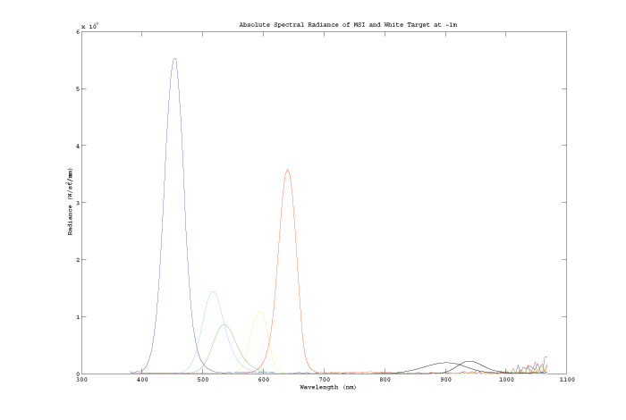
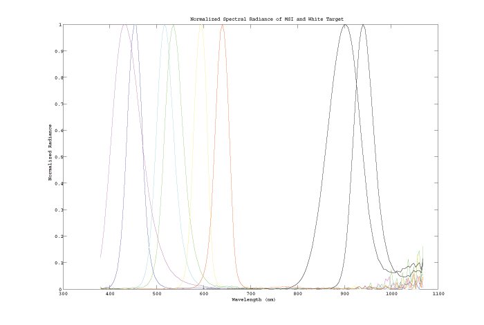
The following two plots show the spectral radiance of the Multispectral Illuminator as measured by SCIEN's Spectrophotometer. The first plot, showing the absolute radiance from the white target, shows the extremely low UV level compared to the other channels. The IR channels are also fairly low, however the sensor is also more sensitive in the IR bands, and thus the practical exposure times for images under visible and IR illumination by the illuminator are effectively the same. The second plot, normalized by radiance for each color channel, clearly shows the lack of coverage from approximately 675nm through 825nm. Unfortunately, because this is a rather strange band for practical applications there are few LEDs that fall within this range. Lastly, the "noise" above ~1,000nm is not actually system noise in the spectrophotometer nor background noise in the lab during the test, but appears to actually be signal generated by the LEDs or some type of fluorescence from materials in the LEDs. A dark spectral reading was taken to verify this hypothesis, and the noise floor is so low that it cannot be seen on these plots.
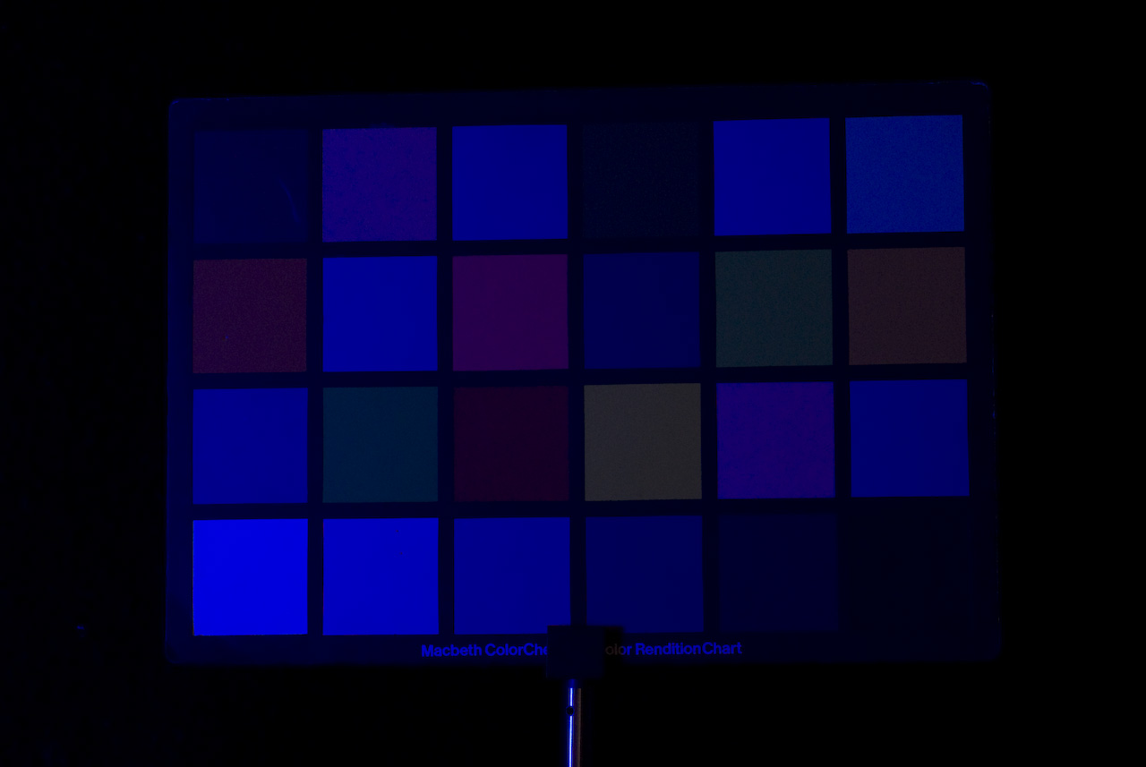
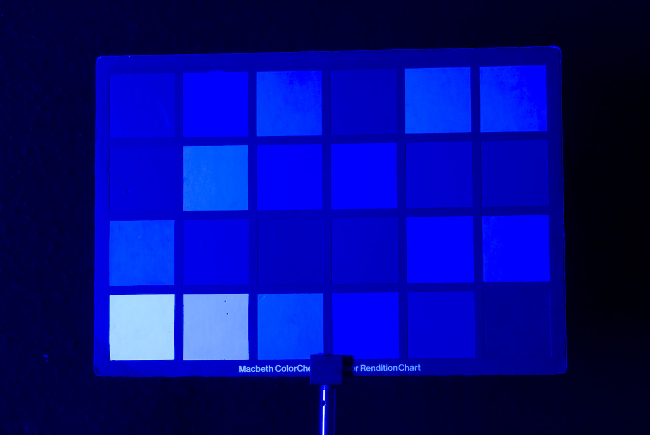
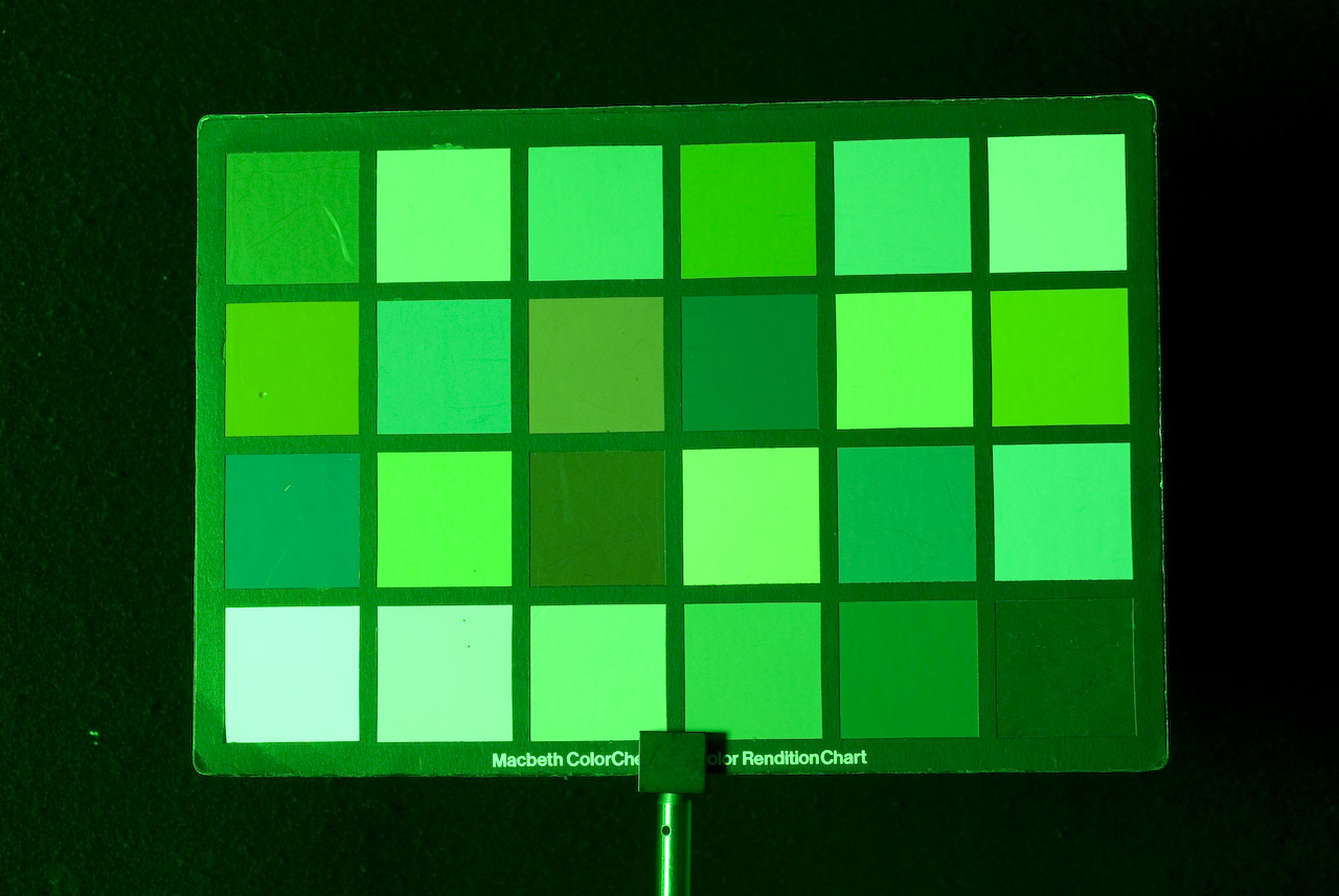
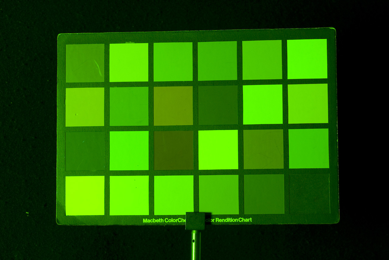
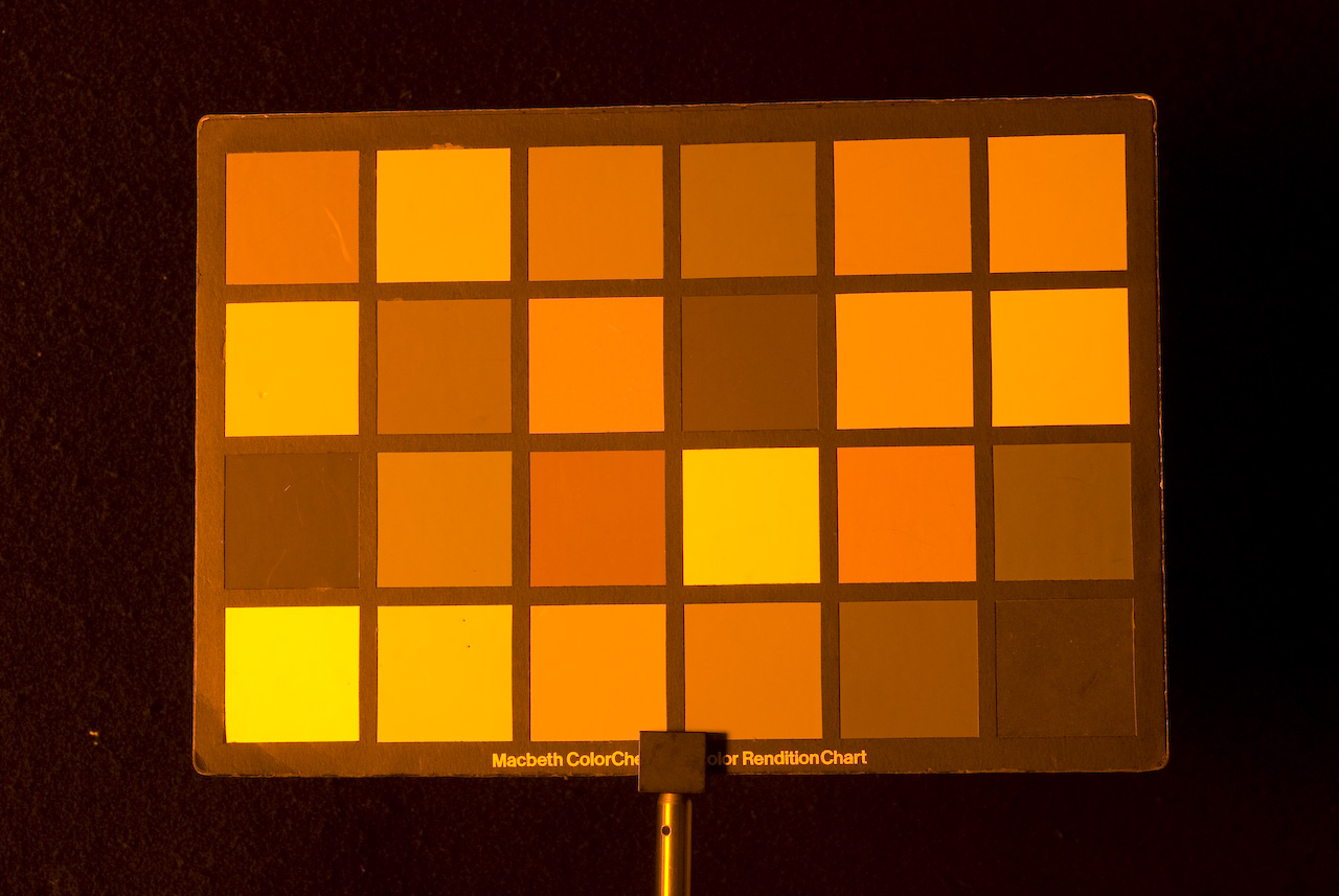
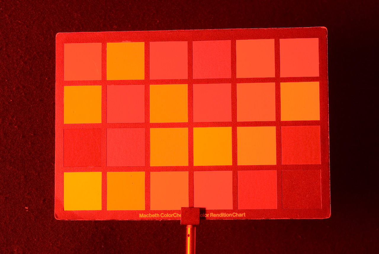
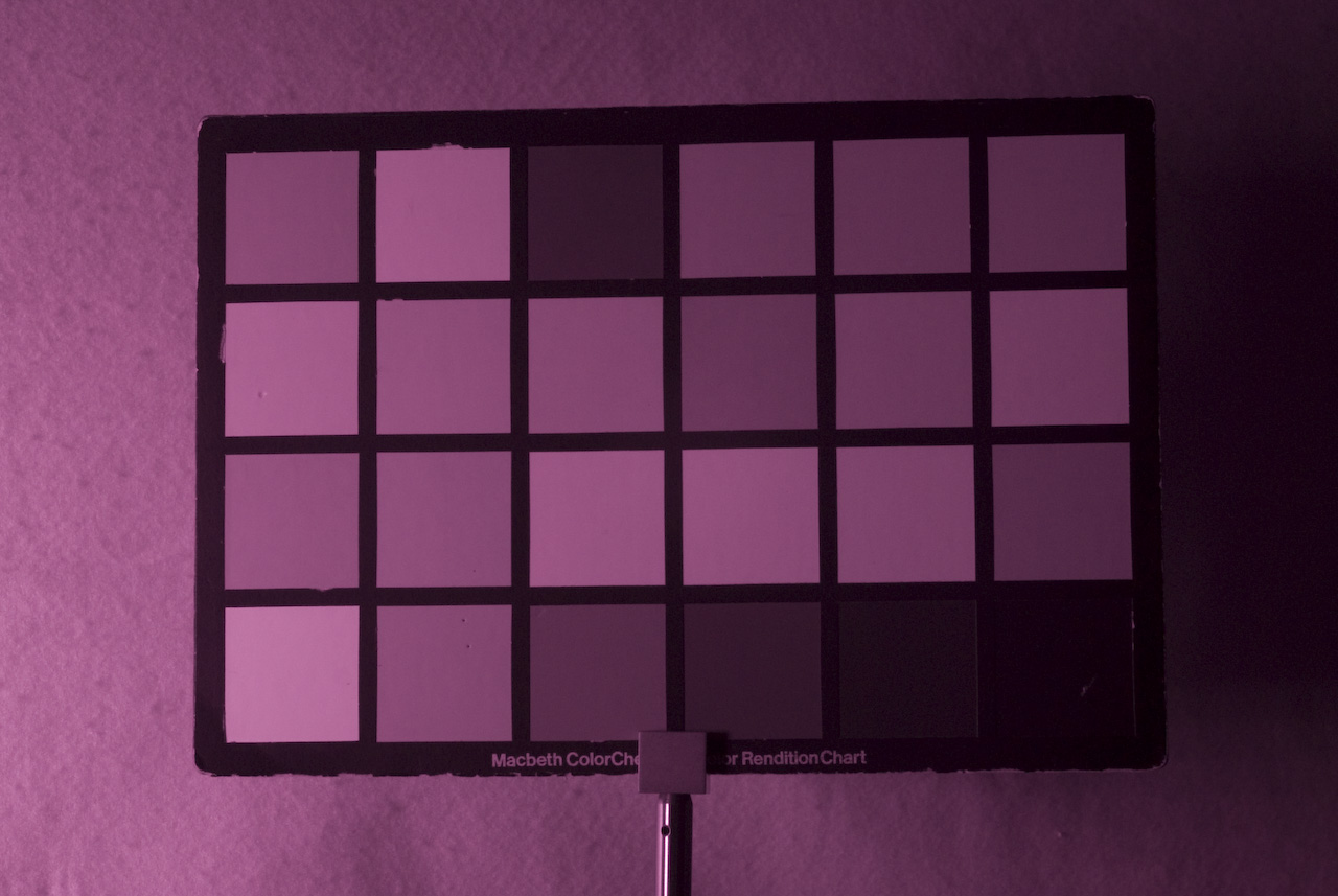
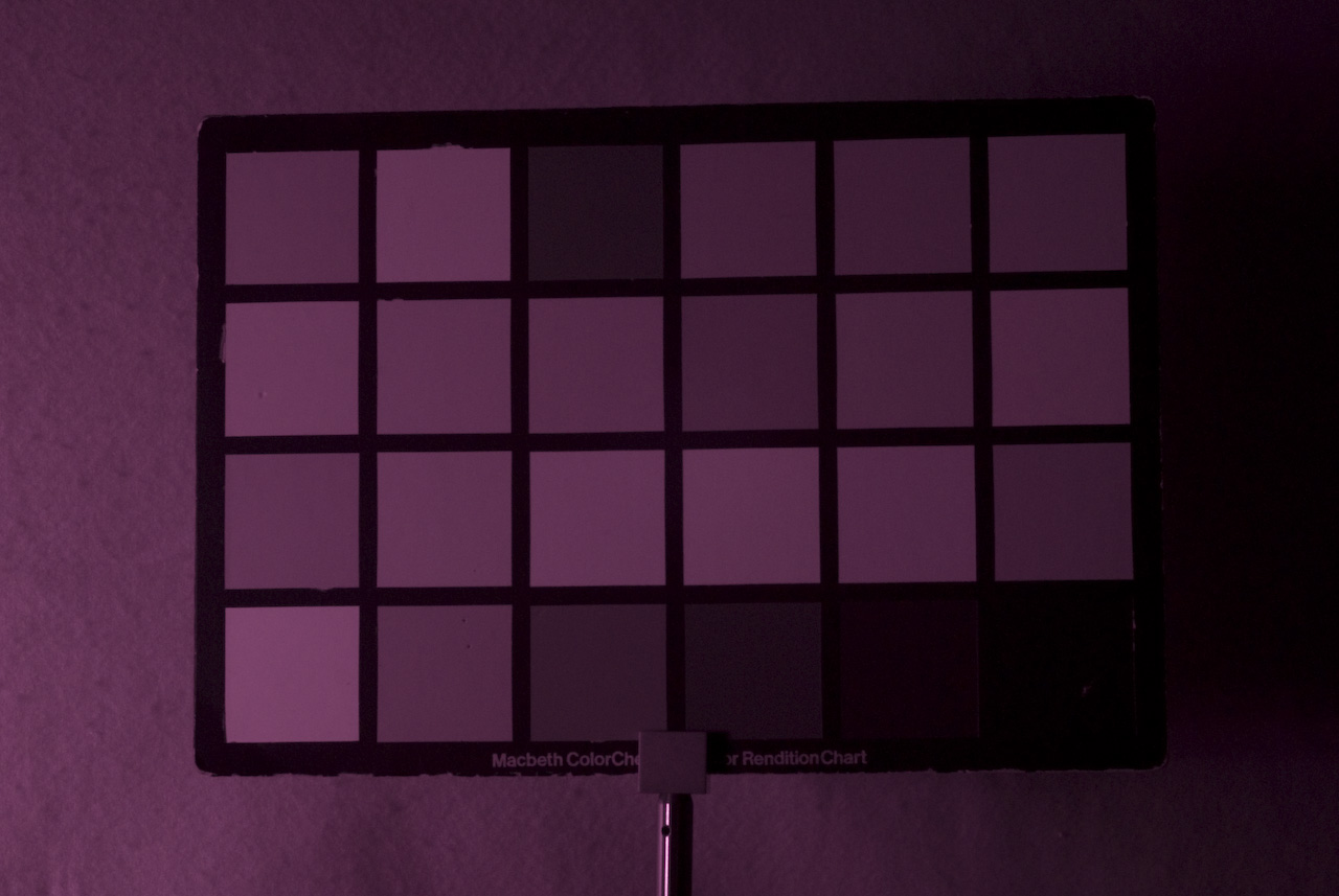
Images of the Macbeth ColorChecker Color Rendition Chart illuminated with: UV, Royal Blue, Cyan, Green, Amber, Red, IR (880nm), IR (940nm).More imagery of actual scenes, plus analysis of the multispectral images, can been seen on the complementary group's project page.
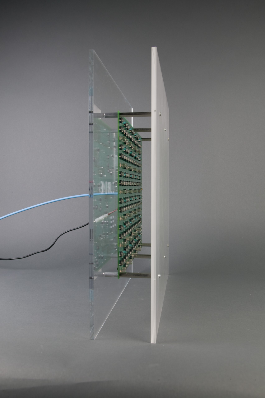
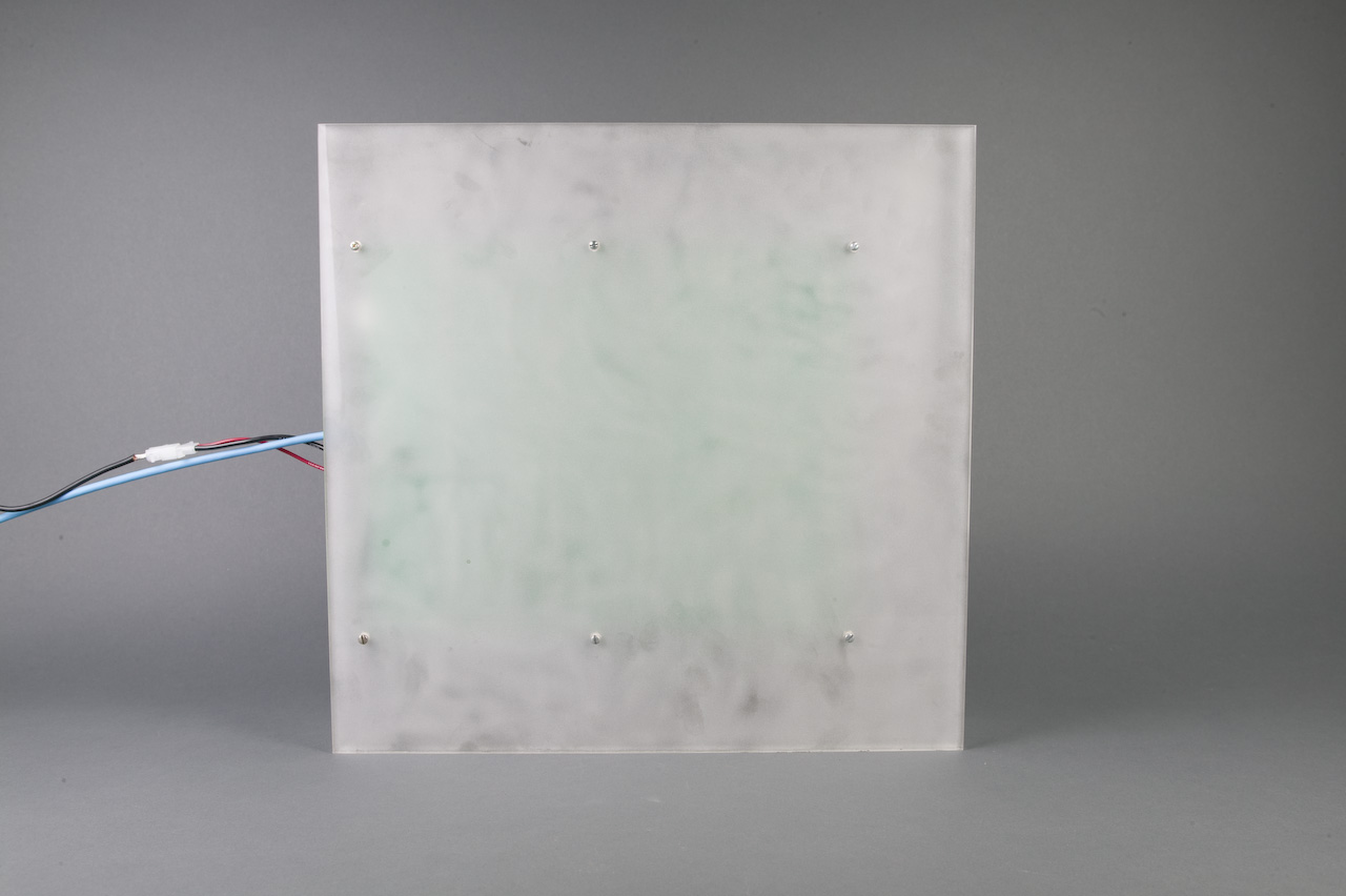
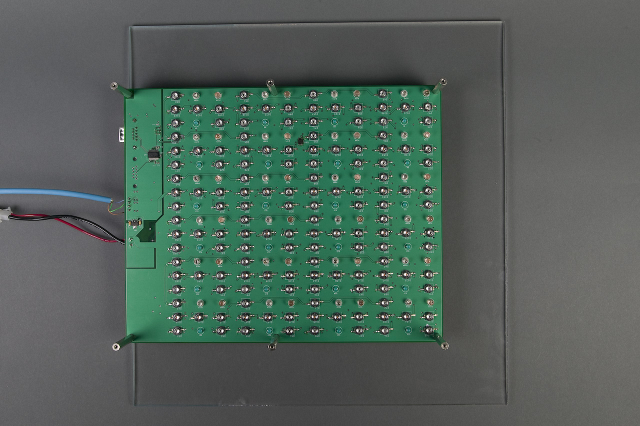
Images of the Multispectral Illuminator itself are available: Back, Side, Front with Diffuser, Front without Diffuser.
Errata / Future Work
The one known error on the PCB is a via that is improperly thermally "relieffed" to a back copper pour which results in a power-ground short. A scalpel was used to correct the relief on all boards currently fabricated.
Unfortunately, the 430nm LED selected for the "UV" area of the spectrum is very poor performing, as can be seen in the absolute radiance plot above. If a new version of the hardware is created, a different UV LED should be used, or perhaps the same LEDs will work and just many more of them will be necessary. Also, doubling of the Royal Blue LEDs proved to be unnecessary, thus the space used by the second Royal Blue channel could be better utilized by UV LEDs.
Appendix I: Supporting Files
10-minute Overview Presentation: (PDF)
Multispectral Illuminator Schematic: (PDF)
Multispectral Illuminator Bill of Materials: (PDF)
Multispectral Illuminator PCB Layout: (Gerber)
Multispectral Illuminator Firmware: (Hex) (Source)
Acknowledgements
I would like to thank Prof. Brian Wandell, Joyce Farrell, and Manu Parmar for their consultation on the design, as well as financial backing for this project.