A Study of Possible Improvements in JPEG
Compression with Applications in High Compression and Wireless Transmission
INTRODUCTION –
Image compression and communication are topics that have significant impact on many aspects of our economy, military, and person lives. For example, improvements in encoding schemes for images increases the reliability and image quality of potentially crucial military satellite image communication systems during battle. Improvements in compression schemes allow both industry and individuals to transfer visual information between terminals at an increased speed therefore increasing productivity. It is evident that even small improvements could have a broad impact. Therefore, alternative compression and encoding schemes are very worthy of the time and effort needed to research them.
PART I of the paper presents a Constant OverLap Add (COLA) approach to windowing the pixels for JPEG compression. Results and comparisons presented show the COLA pixel windowing method is not an improvement over the standard JPEG approach.
PART II of the paper presents a JPEG standard that increases the complexity of the image encoder/decoder, but greatly decreases image degradation when transmitting over a wireless channel. Results presented verify this.
PART I – COLA-JPEG: A
new (not improved) standard for highly compressed images
Methods:
The JPEG standard developed by the Joint Picture Experts Group has become a ubiquitous standard for image compression. The algorithm is lossy with optional extensions for progressive and hierarchical coding. JPEG is capable of handling both color and grey-scale images and is particularly well suited for images with smooth variations [1]. Consequently, JPEG images work well for natural images (such as a picture of your family taken with your digital camera) but not well for text or other images with sharp, well-defined edges.
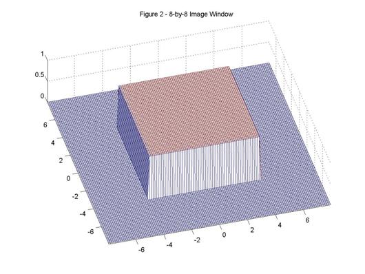
Figure 1 describes the JPEG image compression process. In the first step of the process, the image is windowed using an 8-by-8 rectangular window. A graphic representation of the window is shown in Figure 2. The discrete cosine transform (DCT) separates the image block into spectral sub-bands. The DCT is similar to the discrete Fourier transform: it transforms a signal or image from the spatial domain to the frequency domain. With an input image, A, the spectral coefficients, B, are [2]:
(1.1)
where N1 is the image block width (8 in this case) and N2 is the image block height (also 8 in this case). The quantizer weights the various spectral coefficients according to their importance, with respect to the human visual system. This is the fundamentally lossy step in the compression process that allows for high compression ratios. Finally, a binary encoder uses run length encoding to efficiently store the data [3]. The JPEG is displayed by decoding the binary stream and taking the inverse DCT.
Though JPEG images can be indistinguishable from the source image at a compression ratio of three or so (for color images), the standard has significant problems at high compression ratios. Figure 3 shows a JPEG image with a compression ratio of 9.14.
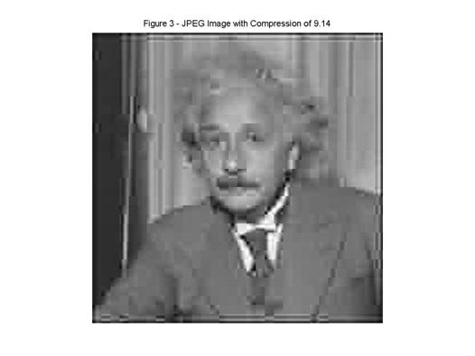
The ‘blockiness’ visible in the image is a general phenomenon apparent in JPEG images with high compression ratios. The human visual system is very acute to sharp edges such as those at the block boundaries. Consequently, the blockiness induces a severe limitation to JPEG compression ratios. The phenomenon is an artifact of processing sub-image size blocks; it would not be present if the entire image were processed in one big DCT/quantization step. Unfortunately, because of constraints such as decompression speed and memory limitations, the image sized DCT/quantization method is not practical.
I have investigated a possible method to mitigate the blockiness apparent in JPEG images with high compression ratios. The compression scheme I propose, named COLA-JPEG, is similar to the JPEG compression scheme with the exception of the window used to parse the image. The COLA-JPEG compression scheme uses the window shown in Figure 4 whereas the JPEG scheme uses the window in Figure 2.
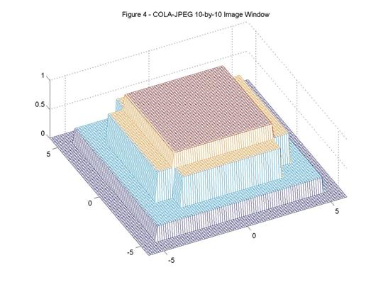
The COLA window is 10-by-10 pixels, has a maximum magnitude of one, a minimum magnitude of one quarter, and a third magnitude of three quarters. The window as created such that if one overlapped the window with itself, with a hopsize of eight, and added, the sum would be a constant value of one. Mathematically,
![]()
(except edge points) (1.2)
where w is the window function and a and b are arbitrary and large. Because of the Constant OverLap Add (COLA) property of the window, it is possible to perfectly reconstruct an image windowed with this function:
![]() (1.3)
(1.3)
So, it is possible to reconstruct the image perfectly when there is no compression, but what happens when the windowed image is heavily quantized? Intuitively the window will provide a smooth transition from one block to the next when high compression ratios would normally cause the JPEG standard to be blocky. However, because the COLA-window is larger than the rectangular window, each COLA block will have to quantized more heavily to achieve the same compression ratios. The end metric for the usefulness of any image compression algorithm is how well it actually works. To that end, I have created a COLA-JPEG compressor/decompressor.
The COLA-JPEG compressor requires a 10-by-10 DCT matrix and a 10-by-10 quantization matrix. The DCT matrix as generated using equation (1.1) and the quantization matrix was generated using the 8-by-8 quantization matrix with the last two rows/columns repeated twice. The quantization table is suboptimal, but improvements are likely to be time consuming and largely ineffective. Figure 5 presents a comparison of JPEG with COLA-JPEG. To ensure fair comparison, each image going across the rows has nearly the same compressed file size.
Results:
Figure 5 –
Comparison of JPEG with COLA JPEG


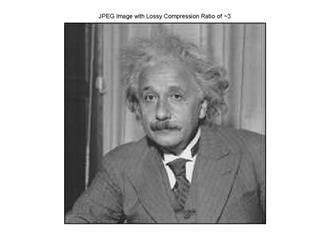
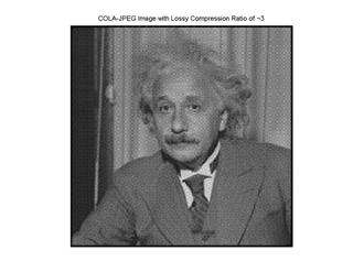

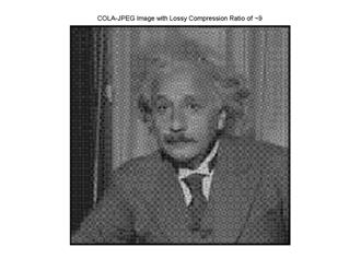
With no compression, as predicted, there is perfect reconstruction. At a compression ratio of 3, the COLA-JPEG is darker than the JPEG. Additionally, the COLA-JPEG appears to have a slight periodic pattern overlaid on top of the image. At a compression ratio of 3, the JPEG is clearly better. At a high compression ratio, where the COLA-JPEG was designed to be better, COLA-JPEG continues to be darker than the JPEG. Additionally, the COLA-JPEG still has the periodic pattern overlaid on top. The COLA-JPEG, however, may be superior to the JPEG in recognizably. Recognizably is a subjective measure, but look at the image a while and it may become evident that Einstein is easier to recognize in COLA-JPEG at a compression ratio of 9 than the JPEG at a compression ratio of 9. It is evident that another test picture is needed to evaluate further the differences in the COLA-JPEG and the JPEG. Figure 6 presents this comparison with a vertical strip pattern.
Figure 6 –
Comparison of JPEG with COLA JPEG
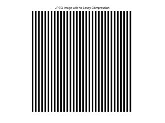
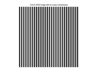
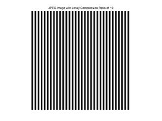
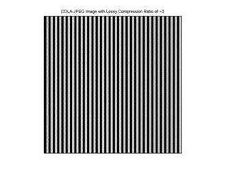
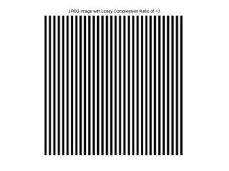
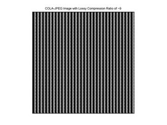
Figure 6 shows that the COLA-JPEG continues to have a darkening effect and a periodic overlay for any appreciable compression ratio. It is evident that the COLA-JPEG offers no advantages to the current JPEG standard. The investigation, however, was interesting from a theoretical point of view and the COLA-JPEG could possibly become advantageous given the proper COLA windowing function.
PART II – JPEGw: A
new image standard for suited for wireless communication
Today’s vision information is increasing being transferred via wireless technologies such as a laptop with a wireless card or a mobile phone with photo-display technology. While it may be possible to transfer the vision information from source to user perfectly, hostile communication environments may make this transfer prohibitively slow. Consequently, it is important to understand the effects of error in vision information communication.
Methods:
To understand the effects of error in vision information communication, I simulate transmitting images over a wireless channel using Matlab. See Figure 7 for a system block diagram. The simulations are very realistic and include the effects of pulse shaping, additive white Gaussian noise, and matched filter detection. This system is valid for an AWGN system, but can be extended to a fading channel with channel inversion power control.
This communication system is composed of eight main interconnected functional blocks. Each of these blocks is described in detail below:
- Discrete Cosine Transform and Quantize - The discrete cosine transform (DCT) separates the image block into spectral sub-bands. With an input image, A, the spectral coefficients, B, are:
(2.1)
where N1 is the image block width (8 in this case) and N2 is the image block height (also 8 in this case). The quantizer weights the various spectral coefficients according to their importance, with respect to the human visual system.
- Binary Encode Signal – Take the output of the quatizer, which ranges from 0 to 255, and convert to an eight bit binary sequence.
- Generate square-root raised cosine pulse train – This block generates the analog (approximated with a discrete time signal of course) signal s(t) that is to be transmitted over the channel. Equation (2.2) shows the baseband time domain representation of the raised cosine pulse shape that is be used in the simulations [4, page 165]:

(2.2)
where β is the roll-off factor and T is the bit period. For the simulations, the roll-off factor is set to 0.5. For simplicity, and without loss of generality, I assume T=1. This baseband pulse shape is continuous time and infinite duration. For the simulation I sampled h(t), truncated h(t), and normalize h(t) to unit energy in the time domain. Given h(t) and the convolutionally coded binary signal y(n), the transmitted signal s(t) is given by (2.3):
![]()
(2.3)
E is the energy in the baseband signal, sk=1 if y(n)=1, and sk=-1 if y(n)=0. Unit energy (E=1) is assumed.
- Simulate AWGN Channel – To simulate the AWGN channel, white Gaussian noise with SNR given in (2.4) is added to the signal s(t) to yield the received signal r(t).
![]()
(2.4)
where E is unity in this case and σ2 is the standard deviation of the noise. Therefore the received signal is:
![]()
(2.5)
where n(t) is additive white Gaussian noise with zero mean and unit variance.
- Matched filter received data with timing error τ=0 – The general structure for a matched filter receiver for binary, antipodal signaling is illustrated in Figure 8 [4, page 234]:

In this case h(t) is the square-root raised cosine pulse shape and T, the symbol period, is one. Note that by not modulating s(t) at some carrier frequency, I have assumed perfect frequency estimation at the receiver. This assumption is justified because, at pedestrian speeds, Doppler is small compared to the carrier frequency which can be hardwired into the receiver.
- Bit
decision – This block is nothing more than a comparator: if g(n) is
negative
 and if g(n) is non-negative
 .
.
- Binary decoder – This block takes blocks of eight bits and converts them to their equivalent base-10 representation.
- IDCT – This block converts the image from the frequency domain back to the time domain for representation.
In addition to simulating the transmission of JPEG, I propose a new JPEG standard (JPEGa) specifically for use on wireless cannels. To offset the affect of the hostile wireless environment, the JPEG is encoded before transmission through the channel (i.e. channel coding). Specifically, encoding the image will allow the JPEGa decoder to correct (some) bits that are flipped during to transmission. The so called Viterbi algorithm, a convolution cannel coding scheme, allows for low bit error rates (BER) even with low signal to noise ratios. Additionally, the Viterbi algorithm does not decrease the rate of the transmission (i.e. the image memory size will stay the same). This makes the Viterbi algorithm ideal for implementation into the JPEGa standard. The algorithm introduces significant complexity challenges and increased memory requirements that boosts the latency of the encoder and decoder. This additional latency has been reduced recently due to improvements in computational technology. The JPEGa simulation system block diagram is shown in Figure 9.
The simulated JPEGa communication system is the same at the JPEG system except for the Convolutional encoder and the Viterbi decoder:
- Convolutionally encode binary signal – This block convolutionally encodes the output of the transducer x(n) according to the following generator sequences:

(2.6)
These generator sequences were taken from Example 10.5 in [5]. The encoded sequence is then given by the equations:
![]()
(2.7)
where y1n and y2n are multiplexed to give the output sequence y(n). The block diagram corresponding to equation (2.7) is presented in Figure 10.
The rate of this code is one-half and the constraint length is three.
- Viterbi decode signal – This block decodes the received sequence using the Viterbi algorithm with a window length of 15. The window length was chosen as a compromise between complexity and error correction capabilities. The decoder minimizes the hamming distance. More information on Viterbi decoding can be found in [5], [6].
Results:
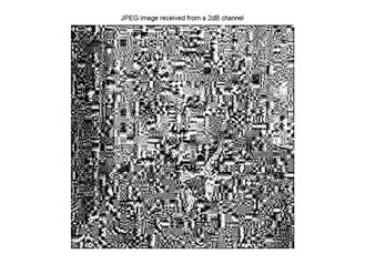
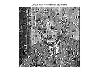
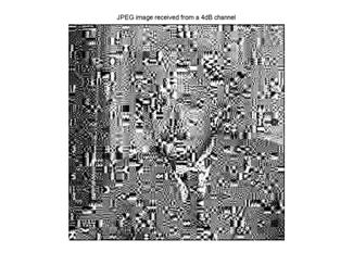
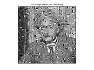
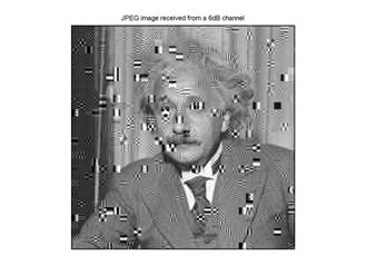
After extensive computing time, the results shown if Figure 11 were complete. In the figure, the left column represents the standard JPEG received after transmission over a noisy channel. The right column represents the JPEGa received after transmission over a noisy channel. Each row represents a constant signal-to-noise ratio.
Figure 11 –
Comparison of JPEG with JPEGa
2dB
4dB
6dB

8dB


10dB
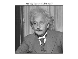

Figure 11 shows that the standard JPEG compression scheme requires at least 10dB for a quality image to be received, and between 6 and 8dB for a discernable image to be received. The JPEGa compression scheme, however, only requires 6dB for a quality image and between 4 and 6dB for a discernable image. A quality image is one with only a few errors, and a discernable image is one just on the boarder of recognition. The JPEGa, therefore is about 4dB better than JPEG for quality images, and is negligibly better for discernable images. Because most applications will require quality images, the JPEGa compression standard is better (in terms of image quality).
While it may be instructive to simulate the transmission of other, more controlled, test patterns, the computation time to do so is prohibitive in this case. It is evident, however, from Figure 11 that the JPEGa scheme has something to offer the world of wireless transmission of visual information.
CONCLUSIONS –
This paper has explored two possible improvements to the JPEG image compression standard. The first proposed improvement, the COLA-JPEG, was aimed at mitigating the blockiness inherent in the JPEG compression scheme at high compression ratios using a Constant OverLap Add window instead of a rectangular window. This proposed improvement, while being instructive, proved to offer no advantage over JPEG. The second proposed improvement, the JPEGa, was aimed at coding the image so that it would be amenable to transmission over hostile wireless channels. This proposed improvement provides a 4dB gain over the JPEG standard for quality reception at the expense of increased complexity.
REFERENCES –
[1] Introduction to JPEG - http://www.faqs.org/faqs/compression-faq/part2/section-6.html
[2] Welcome to the JPEG Tutorial! - http://www.ece.purdue.edu/~ace/jpeg-tut/jpegtut1.html
[3] B. Wandell, Compression and Multiresolution - http://coursework.stanford.edu/coursework/servlet/ShowFile?contentid=36070
[4] T.S. Rappaport, Wireless Communications - Principles and Practice, 2nd Edition, Prentice Hall, 2001.
[5] S. Haykin, Communication Systems. New: Wiley, 2002.
[6] G. L. Stüber, Principles
of