
Foveated Imaging on a Smart Focal Plane
Stuart Kleinfelder
Stanford University
March 12, 1999
Introduction: Enhancing Human Vision
Consider that a good pair of binoculars have a 7 degree field of view, a magnification of 7 times, and light amplification at night (considering the night-adapted iris is 7 mm in diameter and the front element is 35mm in diameter) of 25. Now consider that the human visual system [3] has a field of view of binocular overlap of over 120 degrees, and the 7 degree field of view of a pair of good binoculars is puny indeed - any significant improvement here would be extremely welcome. But increasing the field of view (at fixed magnification) and light gathering by optical means becomes prohibitive in terms of weight and size. Increasing magnification becomes prohibitive due to the concomitant amplification of motion when hand-held. Indeed, except for heavy mechanical-optical motion dampening (which has found only limited application), there have been few improvements in optical binoculars since the introduction of lens coatings several decades ago.
Technologies are now converging to create very compact, light weight vision enhancing systems that can superimpose intelligently and flexibly enhanced vision on top of normal vision via wide-angle "heads-up" type displays. These technologies include the perfection of light amplifying microchannel plates, room temperature infrared detector arrays such as micro-bolometer arrays, smart CMOS imagers, liquid-crystal on silicon (LCOS) displays and others. In contrast with optical binoculars, electro-optical light amplification of up to 10,000 or more is currently achieved in a low-cost, hand-held package. Robust electronic motion compensation can compensate for not only the ego-motion of a hand-held imager, but also motion of the viewed field. With sufficiently high-resolution imagers, even mechanical zoom lenses can be replaced with electronic zoom features, and wide-angle optics become much lighter and easier to design with sensitive electronic imaging where light gathering and input aperture are not a significant issue.
Data Volume and Bandwidth in a Full-Resolution,
Full-Speed, Wide-Angle Vision Enhancement System.
Unfortunately, creating a wide-angle vision system with sufficient resolution is difficult. Consider a wide-angle lens of 90 degrees field of view (a ~21 mm lens on a typical 35mm camera). The spatial sensitivity of the eye peaks at about 50-60 cycles per degree. To generate that spatial frequency requires 120 pixels per degree or, for our 21 mm lens, 10,800 pixels in both x and y, for a total of 117 million pixels assuming a square field of view. At 60 frames per second, one is expected to process 7 giga-pixels per second. Even if one were to compromise and lower the resolution to the lower-end spatial resolution of the eye, one is still dealing with over a giga-pixel per second of data. What's worse, 60 frames per second may not be sufficient for busy or dangerous environments that include lots of disorienting shear-inducing motion and susceptibility to aliasing, such as when running, flying an airplane or driving a truck off-road, leading one to wish for many times higher frame rates, and bumping data rates back up to about 10 giga-pixels/second. Without the requirement of human-portability, it is certainly possible to process this much information, but it is interesting to note that no continuously-operating electronic camera system has achieved even 100 times less throughput.
Space-Time-Foveation as a Means of Bandwidth Management.
The above resolution and bandwidth scenario may seem far-fetched now, but time will make it mundane. The resolution of today's high-end digital cameras are only about 1/10 of that resolution, but advances in fabrication density and yield will allow this level of improvement within 10 years. Bandwidth barriers will yield to increasing parallelism and improved data links such as arrays of integrated laser diodes. However, this sort of brute-force solution is unnecessary. Instead of using as a benchmark the maximum resolution of the human eye over the entire vision system, at maximum data rates all of the time, adapting to the limitations of the human vision can allow vastly lower bandwidth requirements and concomitant reductions in power consumption, etc. The latter is important - if each sensor and display pixel-pair requires just 1 microwatt to operate, the total would be 100 watts! This paper explores the benefits and means of foveated imaging on the focal plane array.
Foveated Imaging Algorithm.
This demonstration is based on the work of W.S. Geisler and J.S. Perry [1,2], who have demonstrated real-time foveation of monochrome video sequences on a Pentium-class computer. Their two papers describe two generations of work. The earlier did not benefit from multi-resolution pyramids [4,13], but computed variable-sized super-pixel blocks that averaged many ordinary pixels oriented in regular square rings surrounding the foveation point, with each ring increasing in size and coarseness with increased radius. The second generation used laplacian pyramids, with interpolation and "blending" between resolution levels. Their later work was oriented toward video compression, and was not presented in sufficient detail for direct replication. Our purposes are somewhat different - aiming toward implementation in a fairly simple VLSI-friendly architecture, but the following demonstrations are generally similar to their latter generation of work. All algorithms are implemented in Matlab.
All of the various algorithm starts by determining several constants
and variables. As proposed in [1], constants include:
| xs=640, ys=640 | The size of the image in x and y |
| fovx=320, fovy=320 | The x and y coordinates of the foveation point. |
| ct0=1/64 | Minimum contrast threshold. |
| alpha=0.106 | Spatial frequency decay constant. |
| e2=2.3 | Half-resolution eccentricity. |
| dotpitch=0.28x10⁻³m | Dot pitch in meters at 72 dots per inch. |
| viewdist=0.305 | Viewing distance of 1 foot, in meters. |
Table 1. Typical foveation parameters.
Informal experiments with different images and different viewing conditions resulted in the tweeking of several of these parameters in order to provide more dramatic results under local conditions. For the simulations shown in this work, the parameter alpha was increased by 50% and the parameter e2 was decreased by 50%. This was done to enhance the degree of foveation so that more pronounced effects are visible over the relatively small images used.
From the above data, a mesh ec the size of the original image containing the eccentricity in degrees of each pixel from the foveation point is computed:
[ex, ey] = meshgrid(-fovx+1:xs-fovx, -fovy+1:ys-fovy);
ec = 180*atan((dotpitch.*sqrt(ex.^2+ey.^2))./viewdist)/pi+0.001;
Equation 1 in reference [1] offers the following formula for the threshold of contrast sensitivity CT in human vision, a function of the above constants and f, the spatial frequency, and e, the eccentricity:
CT(f,e)=ct0*exp(alpha*f*(e+e2)/e2)
Setting the contrast threshold CT(f,e) to a maximum of 1, and solving for f leads to a formula in matrix form for f, the raw spatial frequency in cycles per degree at every pixel:
fmat = ((((e2./alpha).*log(1/cd0))-e2)./(ec+e2));
We need to compute the maximum frequency in cycles per degree that the display device is capable of, while taking into account the eccentricity of viewing:
eradius=dotpitch.*sqrt(ex.^2+ey.^2);
maxfreq = pi./((atan((eradius+dotpitch)./viewdist)-atan((eradius-dotpitch)./viewdist)).*180);
Normalizing to the maximum spatial frequency of the display device based on viewing distance and eccentricity:
levelmat = maxfreq./fmat;
Thus, if the maximum frequency of the display device equals the maximum visible frequency, levelmat is 1. If the maximum visible frequency is lower, levelmat will be larger than one - at a higher level in the pyramid.
This image ('m640.tif') is stored in tiff format and is loaded into matlab with the command:
im=imread('m640.tif','tiff');
A multi-resolution gaussian pyramid is constructed:
[pyr pind]=buildGpyr(im);
[levels junk]=size(pind);
The appropriate pyramid level for each pixel is truncated to fit within the available pyramid levels:
fovea=max(1,min(levels, max(levelmat,1)));
A 3-D matrix is constructed in which each pyramid level is upblurred by an appropriate factor so that the size of each pyramid level is fit to the original image size. This makes interpolation between pyramid levels easy:
psc=zeros(ys,xs,levels);
for k=1:min(levels,ceil(max(max(fovea))));
psc(:,:,k)=imcrop(upBlur(pyrBand(pyr,pind,k),k-1),[1 1 xs-1 ys-1]);
end;
Meshgrids for the 3-D interpolation are created, and a linear (in this case) interpolation between the pyramid levels, as determined pixel by pixel by the fovea matrix, is computed:
x=meshgrid(1:1:ys);
x=x(1:xs,:);
y=meshgrid(1:1:ys)';
y=y(1:xs,:);
b=interp3(psc,x,y,fovea,'linear');
If the image is monochrome, b is the output image. If in color, the above steps are performed on R,G and B individually, and the output image is recombined.
The above is a description of the basic algorithm that results in a smoothly foveated image, but entails significant computational effort. Several different algorithms were developed with varying levels of computational efficiency and residual visual artifacts. In principle, all of these algorithms should result in images which, when viewed under the correct conditions (correct viewing distance, eye tracking, etc.), are indistinguishable from the original image. In practice, when viewed under static conditions, the various compression artifacts will be dramatically evident and more-or-less objectionable.
Foveated Imaging Demonstrations
In the following examples, the foveation parameters given in table 1 were tweeked to provide a slightly more dramatic foveation effect than actually expected at the viewing distances given below. This is to more easily show higher level of foveation given the small image sizes used. For a test image, a color photograph of a mosaic found on Stanford's Memorial Church was shot by this author and scanned at 24 bit color depth (8 bits each of red, green and blue), and a size of 640 by 640 color pixels. The picture is therefore described in 1,228,800 bytes with no compression used. It is shown here in full resolution:
Figure 1. Normal (unfoveated) test image, full resolution.
Figure 2 shows a foveated image, produced with an intended viewing distance of 0.25 meters. At this distance, the apparent foveation is modest. View the image from about 10 inches from the monitor with one eye centered on the image. Focus on the very center of the image. Without moving your eyes focus, try to tell if you can see if the image is foveated. Compare to the original image. Remember that, for these simulations, the foveation parameters were changed to increase the amount of foveation for the purpose of illustration - you may have to view from closer than the "viewing distance" states. Also note that, at this distance, the fovea of the eye has greater resolution than the computer monitor. Hence, the central full-resolution fovea region is large. Only in the periphery, where the eyes resolution drops below that of the monitor, is there significant blurring.

Figure 2. Foveated test image at 0.25 meter viewing distance (using enhanced foveation parameters). This level of foveation resulted in compresion of the image by a factor of 2.6.
Figure 3 shows a plot of the shape of the fovea used in the producttion of figure 2, with 2^level weighting.
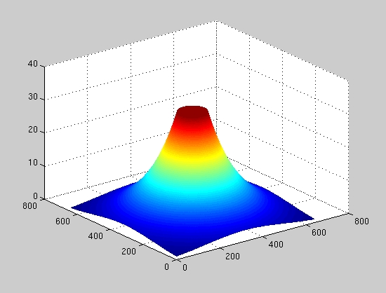
Figure 3. Contour plot of fovea level map used to produce figure 1.
The smooth transition between levels as seen in figure 2 is striking in contrast to the following picture, which used nearest-level interpolation instead of linear interpolation. Concentric circular bands are seen - these are concentric bands from the pyramid, each upblurred to the same resolution as the original image. Try viewing figure 4 from about 10 inches. If the foveation is sufficient, in principle you should not see the bands.

Figure 4. Foveated test image at 0.25 meter viewing distance, nearest-level interpolation. This foveation resulted in an image compression factor of 2.5.
The next image demonstrates the dramatic foveation that occurs if the viewing distance is very small. If one viewed the image from a very small distance, the eye would have extremely high resolution of the center foveation point (well above that of the monitor), but the angular eccentricity of the periphery would be high. Therefore, one would expect the resolution fall-off to be more rapid than in the first case. Try viewing figure 3 from a distance of 1 inch (press your nose to the screen!).

Figure 5. Foveated test image at 2.5 cm viewing distance. This degree of foveation resulted in image compression by a factor of 5.7.
If one viewed the original image from a great distance, the eye would not be able to see the image at full resolution. In addition, the angular difference between the foveation point and the periphery is small, and so the difference in foveation between the center and the periphery is small. Therefore, the foveated image is significantly blurred in a fairly uniform fashion (see figure 6).

Figure 6. Foveated test image at 2.5 meter viewing distance. This foveation resulted in data compression by a factor of 5.9.
The use of super-pixels (groups of ordinary pixels) can be leveraged to reduce the computational complexity of the foveation algorithm. This approach is similar to that described in [XXX]. Rather than a smooth pixel-by-pixel interpolation, one can use coarser pixels at the periphery than in the foveal center. For the following example, the filter for the upBlur function used in re-sizing the gaussian pyramid to constructing the 3-D interpolation matrix was changed from a binomial blur to zero blur, which results in square pixels changing in size by factors of two between levels. Fine pixels (normal resolution) are formed at level 1 of the pyramid, 2 by 2 pixel super-pixels at level 2, 4 by 4 at level 3, etc. These "super-pixels" should be not be perceptible under the right viewing conditions. Figure 7 shows a foveated image at 0.25 meter (~10 inch) viewing distance using increasingly larger pixels at larger deviations from the foveal center. Try viewing the image as before (10 inch distance, focus on the center) and seeing if you can distinguish the super-pixels.

Figure 7. Foveated test image at 0.25 meter viewing distance, super-pixel algorithm. This style of foveation resulted in a compression by a factor of 1.85.
Considerations for Implementation of Foveal
Vision on the Focal Plane.
If one is to perform foveal imaging on the focal-plane array, one needs to be sensitive to the kinds of computations that can be implemented in compact and fast VLSI. Compactness, in particular, is important, since in CMOS imagers, the sensitive imaging area is compromised by the inclusion of additional circuitry. Other criteria that tend to make VLSI systems practical in a conventional sense include the use of manhattan (x-y) geometry rather than organic (i.e., circular) geometry, and peripherally addressed control vs. pixel independence (address-event architecture). Naievely, an address-event architecture [XXX] appears well-suited to vision applications, as it resembles the operation of the human eye in many respects. Likewise, implementing circuiar foveal sensors [XXX] also appears to be directly applicable. However, neither of these are well suited to electronically adapting the foveal focus. A circular foveal sensor would need to be mechanically aimed in order to focus the foveal center at different points in the field of view. Likewise, the address-event scheme has no intrinsic way of coordinating a region of pixels to act as a foveal center, as all pixels are, by definition, acting independently.
An architecture is proposed here that plays to the traditional strengths of conventional CMOS imager design, yet allows electronic control over the position of the foveal center, the peak magnitude, width and shape of the resolution fall-off from the center, allows for rapid changes in the characteristics of the fovea, and even allows for digital magnification, electronic dithering for super-resolution enhancement, and multiple foveal focus points. Dubbed FOVIS (Foveal Opto-electronic Vision Integrated System), this flexible architecture can be implemented in current CMOS analog or digital imaging sensors without difficulty.
Foveal Opto-electronic Vision Integrated System (FOVIS)
Since the object of foveal vision is to maintain or enhance resolution at the foveal focus and reduce resolution gracefully towards the periphery of focus, the FOVIS architecture starts with a pixel design in which detector elements can be optionally combined in both x and y to create lower-resolution super-pixels. Peripheral control can then set the resolution of each super-row and column with arbitrary freedom. The FOVIS architecture allows:
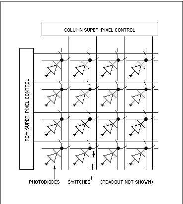
Figure 8: Super-pixel sensor mesh array with row/column control.
Two switches per sensor diode are needed. If every row and column switch is open, none of the diodes are connected, and the entire array operates at full resolution (4x4 in figure 8). If every other row and column switch is closed, then 2x2 super-pixels are created that average the light gathered among 4 pixels at a time, and the resolution of the array is reduced by a factor of two in both x and y (yeilding a 2x2 array seen in figure 8). Thus, the array can be configured for almost any resolution.
Figure 9 also shows the schematic seen in figure 8, but in VLSI form and with 8x8 pixels with row and column super-pixel control switches but without readout circuitry. The pixels are drawn using 0.18 micron design rules and are only 2 by 2 microns in size. With this pixel size, a ~1 square inch circuit will offer over 100,000,000 pixels.
![]()
Figure 9: Mesh-connected CMOS photodiode sensors with X and
Y super-pixel
peripheral control for foveal imaging (readout not shown).
It is not necessary for the resolution control to be uniform - control over resolution can differ between different super-pixel columns and/or rows. If the foveal focus is in the center of the array, for example, the column control for super-pixels can be 8 wide at the edges, 4 wide a little closer in, 2 wide near the foveal focus, and 1 wide within the foveal focus. Likewise, the row control can vary the resolution in much the same fashion, resulting in a range of super-pixel sizes from 8x8 in the corners to 1x1 in the center. The resulting foveated vision is similar in character to the above super-pixel example seen in figure 6, except that the shape of the foveation has an x-y cross shape that approximates the concentric circular rings seen above. The cross shape is slightly less efficient than the ring shape, in that "too much" information is carried at the extremes of the crosses arms. However, this reduced efficiency is small compared to the benefit of simple x-y addressing. To create circular bands in an x-y array would require pixel-by-pixel programming of the mesh array. If desired, a hexagonal array could be formed that would more closely approximate the circular bands using a 3-axis peripheral control.
Not only does the FOVIS architecture allow foveated imaging, but it performs it without the need for any external calculations such forming multi-resolution pyramids or interpolation, etc. Each super-pixel computes an average analogically and in parallel.
Flexible Programmable Foveation Profiles
The FOVIS architecture allows flexible programming of the size and contours of the foveation. This is accomplished by creating programmable row and column peripheral super-pixel control so that the width of each and every row and column can be individually determined.
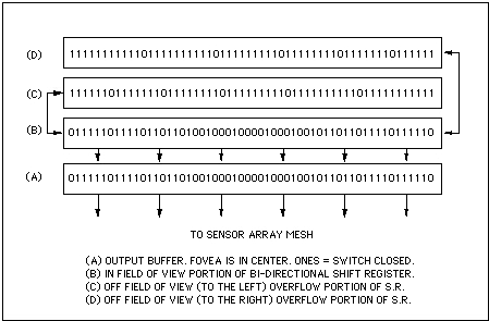
Figure 10: Buffered bi-directional shift-register peripheral
row/column foveal focus coordinate control.
The FOVIS architecture allows for very fast repositioning of the foveation focus that, frame-to-frame, can continually track an external reference (i.e., from eye-tracking hardware). This is accomplished by implementing the peripheral row and column controls as bi-directional shift registers (see figure 10). Moving the data in the column shift registers to the right shifts the foveal focus to the right. Moving the data in the row control upward moves the foveal focus upward. Doing both moves the foveal focus north-east. The row and column controls continually compares it's position against the external reference and clocks the shift register the appropriate amount to match the external reference (see figure 11, below). At the start of each frame, the shift register data is clocked into a buffer that freezes it's position for that frame, and then allows the shift register to resume tracking. Since the foveal point can shift all the way to the corners of the imager, each shift-register is three times as large as the dimensions of the array so that the data in the registers can slide "off" the array and still be stored for when the eye moves back from the edge. Note that programmable foveal fall-off can continue normally at these extremes. In addition, the position control can naturally incorporate features allowing electronic dither for super-resolution enhancement over multiple frames, motion compensation offsets, panning and other effects.
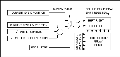
Figure 11: Simplified X-Y foveal focus coordinate control scheme.
Programmable Visual Effects
While the foveal profile can be changed by up-loading different contents into the row and column shift registers, the peripheral X-Y control can also include a capability for multiple programs that can be instantly switched. This is accomplished by designing the shift registers to be more than one bit deep and switching between different levels in the register, which can be accomplished instantaneously. Programs might include:
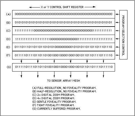
Figure 12: Scheme for instantaneous switching between pre-loaded programs.
Space-Time Foveation
Not only can the FOVIS vary resolution in space, but it can do so in time as well with one more extension of the above programming facility. Foveation in time is motivated by the notion that the foveal focus requires more attention not only in spatial resolution, but perhaps faster "frame" rates as well, while slower updates may suffice in the larger periphery. This strategy can further reduce over-all data bandwidth while permitting normal "frame" rates or even enhanced rates at the fovea.
This extension would allow subsets of programs (as above in figure 12) to be rapidly switched in a regular fashion. Each sub-program could, for example, represent a different resolution level (see figure 13, below), and by switching between programs, each level could be activated and read-out separately from other levels. The higher-resolution levels could be read out many more times than low-resolution levels, for example.
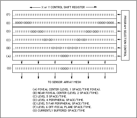
Figure 13: Space-time foveation iterative program. Programs
iterate in time
and space (foveation level) by cycling programs addressing the
fovea (A) through to the periphery (F). Each level may be activated with
different frequency, for example, (A) more than (B) more than (C)...,
in order provide higher "frame" rates near the foveal center.
Simulating the FOVIS Architecture
It is possible to simulate the appearance of row/column foveation. The FOVIS architecture allows an arbitrary foveal profile, and here we use a simple binary-weighted profile, seen in figure 14 (below), which is somewhat similar to the profile seen in figure 3. This profile is constructed by the intersection of identical x and y profiles. Compared to the circular profile of figure 3, it is a little more square. The more square profile is a side-effect of adhering to the conventional VLSI design practice of using exclusively orthogonal geometry. It is possible to produce more circular profiles if "non-manhattan" geometry can be employed.
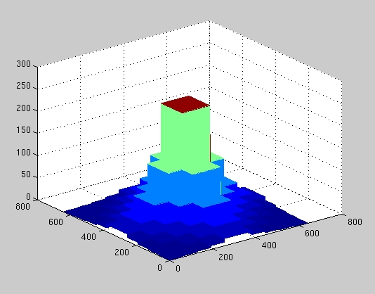
Figure 14. Example foveal profile formed by X and Y projection.
Unlike the foveal imaging simulations performed above, the FOVIS architecture does not use multi-resolution pyramids or interpolation. Instead, the pixel values within each super-pixel values are merely averaged. In the VLSI implementation, the averaging is achieved in parallel within each super-pixel by charge sharing - no external computation is needed. In the simulation, an iterative algorithm was needed to form each super-pixel and average the values from the original image. The resulting image is seen below in figure 15.

Figure 15. Example foveated image resulting from using the FOVIS architecture. This style of foveation resulted in data compression by a factor of 2.3.
The image shown in figure 15 may best be compared to that of figure 7. Both use "super-pixels," but the figure 7 picture required the construction and interpolation of multi-resolution pyramids, while figure 15, if implemented in VLSI in the fashion described above, requires no post-processing. Although the foveation profile is only approximately similar to the foveation profile used in figure 7, the visual appearance and resulting compression compares favorably with that of figure 7.
Summary and Conclusions:
In the future, extremely large imaging sensors will become possible, leading to the development of high-resolution, wide-angle vision enhancing systems. However, these systems will produce unnecessarily large amounts of data if simple brute-force methods are used. Foveated image processing has the potential to substantially reduce data bandwidth and power consumption by apportioning resolution based on the capabilities of the human visual system. Implementation of simulated foveal vision that uses multi-resolution pyramids and various interpolation schemes demonstrated its effects and artifacts. A presentation of a foveal vision architecture then followed. This architecture (FOVIS) is amenable to implementation in VLSI, and does not require the construction and interpolation of multi-resolution pyramids. Instead, it uses a simple X-Y projective formation of variable resolution "super-pixels" in which an intrinsic averaging among sub-elements occurs over the whole focal plane in parallel, and no external signal processing is required. Simple programmable extensions to the architecture allows dithering for super-resolution, paning for motion-compensation, digital zoom, and instantaneous changes of resolution and foveation profiles. Foveation in time as well as space can be accomplished as well, in which different resolution levels can be accessed with different frequency so that, for example, the foveal center is updated much faster than the far periphery, further optimizing the use of available bandwidth. A simulation of the architecture shows foveation results that compare well with the pyramid schemes in both visual character and data compression factors.
Acknowledgments:
William Overall and I collaborated on understanding and implementing the Geisler and Perry foveation algorithm - his assistance was invaluable. Thanks also go to Professors Wandell, Pease and El Gamal for their assistance and patience with some of my more ill-considered and off-the-wall ideas. Thanks are also due to Michael Bax for his swift and sure assistance.
References: