VASARI System
(Visual Arts System for Archiving and Retrieval of Images)
The VASARI system, funded by the European Commission’s ESPRIT program, was the first attempt to capture paintings reliably, with good repeatability, at a high resolution, and on a lasting medium.
In designing a system to capture a painting, the first consideration was protection of the painting. The painting had to be always in a vertical position, with special reinforcements. The entire process had to be quick; paintings could not long be held under direct light without potential damage. Minimal movement of the painting was an important factor as well. As museum research projects are not well funded, money was also a consideration, and where possible, commercial parts were used to reduce the cost.
Mechanics
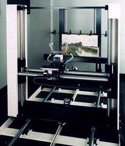
The VASARI system (shown above) consists of an XYZ positioning system mounted on a rigid steel base with vibration damping blocks on a concrete floor. The painting is mounted vertically, perpendicular to the system’s Z-axis, which is manually moved along two rails to move closer to the painting. Calibration charts are mounted flush with the painting. The painting is divided into "tiles" of 3kx2k, overlapping by around 200 pixels, and the camera subsystem uses a stepper-motor to move automatically along the XY axis to capture these tiles. Two 24V, 250 W DC tungsten halogen lamps send light through fiber-optic light guides, which keeps the main source of heat away from the painting. These lights move with the camera so that each frame is illuminated consistently. The positioning system has a better than 10 um accuracy. This is even higher than required, due to the compensation in the tile overlapping.
Camera
systemThe VASARI system uses a commercial camera — the Kontron ProgRes 3000, with a high resolution of 3000 x 2320 pels. It contains a 12-bit area CCD. An 8-bit A/D converter translates the data into digital format. The loss of the extra four bits is not significant, due to the noise characteristics of the signal. The tiles are divided such that the entire painting is covered at a 20 pixel/mm resolution, which is sufficient to detect cracks in the painting of 0.1 mm wide.
The camera uses a monochrome sensor with seven different broadband filters. These filters have a bandwidth of 70 nm, and cover the visible spectrum from 400 to 700 nm in steps of 50 nm. Originally, the system was to have 11 filters with total spectral reconstruction. J. Hardeberg did an analysis showing that with 11 filters and 12 bits of data per pixel, a very accurate spectral reconstruction could be accomplished. This is because classical paintings tend to have smooth spectral properties in their pigments. An interesting point to note is that this cannot be used for modern paintings, which tend to use fluorescents, acrylic, and other imported media. Further analysis showed that although dropping down to seven filters would lose some color data, the proportion of extra time spent gathering the data was not reasonable. The plan of storing each captured pixel with its reconstructed spectrum also was abandoned since the storage requirements would be too large. Instead, the corresponding tristimulus values are stored.
CCD Area camera brief description
Photons from the illuminated painting frame pass through one of the filters and hit the CCD image sensor where they are turned into electrons. These electrons are collected and amplified to a level selected so that the digital output completely fills the available range of values (0-255). The resulting charges are fed into output nodes that convert the charges into voltages. The A/D converter takes these analog voltages and converts them into an eight-bit digital number that is transmitted to the workstation and stored.
Sun workstation and SBus translator
The entire system is controlled by a Sun SPARC workstation with 32 MB of RAM, a 24 bit graphics system, and an extra 2 GB of hard disk storage. This controls the camera movement, filter switching, and data gathering.
Originally, to transmit the data from the camera subsystem to the Sun workstation, the data was captured in RAM at the camera subsystem and forwarded to the Sun over an Ethernet connection. An SBus connection made it possible to connect the camera subsystem directly to the Sun, which reduced the frame grab time, the rate limiting step in image acquisition. Although the true rate limiting step in the process is the transport of paintings from the museums to the lab, which can only be done on an order of two per day, minimizing the time that a painting must be exposed to potentially damaging light is of great importance.
SBus protocol description
The SBus uses a 96-pin cable to transfer data between a Sun workstation, which holds the SBus board, and an independent device (the A/D converter/Memory RAM installed in the camera subsystem). Analog data from the camera is digitized and put into camera data memory where the SBus can extract it for processing.
The protocol can be used in a variety of configurations, but they differ little from the most common use. The design is optimal for applications such as the VASARI and MARC systems, where space is limited and high performance is required.
The SBus consists of three components: the master, slave, and controller. The controller provides a clock of fixed frequency in the range of 16.67 MHz to 25 MHz for synchronous operation. To keep power requirements low, no signal is driven by two outputs during the same clock cycle. This prevents contention, which results in unreliable operation and excessive power dissipation.
There are a total of 82 signals used for information and control. The controller controls and oversees the data transfer between the master and slave using a clock and reset, an address bus with a strobe to indicate readiness, a signal to grant the data bus to the master, and a signal to select the slave for data transfer. The data bus is transferred between the slave and master, with the master indicating the size of the data transferred and whether the action being performed is read or write. The master has a request signal, to request a data transfer; and the slave has an interrupt request bus to indicate that it has data ready to be transferred.
A typical cycle will occur as follows.
The process : Acquisition, Calibration, and Mosaicing
Acquisition
Manual steps :
The painting is brought to the lab, mounted on the easel with the calibration charts. The light guides are adjusted for maximum illumination and uniformity, and the camera is manually focused. The camera is roughly positioned on the Z-axis.
Automatic steps :
The focus is now automatic, using the 550 nm filter to illuminate a section of the painting. The camera is thus accurately positioned on the Z-axis.
An acquisition software program is given the size of the painting and the placement of the calibration targets. Seven images (through the seven filters) are taken of each 3k x 2k "tile" with an overlap of 20 pels and each calibration chart.
Acquisition is complete and the painting is now brought back to the museum. Calibration is now started.
Calibration
The calibration charts mounted with the painting are captured and used as follows.
Mosaicing
The XYZ sub-images generated in the calibration stage are then joined together into a mosaic to recreate the painting in an XYZ image format. Two adjacent tiles are laid together, and 60 points are sampled in the overlap region of one of the regions. The corresponding 60 points in the other region are sampled, and a straight-line fit is generated. The average of the displacements is calculated to determine the offset of the two images. This is repeated for each tile in the painting.
Storage
The raw data and the XYZ values are stored. Originally, RGB values were also stored, but due to the storage space limitations, these are now calculated on demand.
Color
As described, the images are captured using the CIE XYZ standard color space. CIELAB color coordinates are derived from the XYZ values. XYZ values are calculated by multiplying the matrix of camera responses through each filter with each filter value. This is used to calibrate the color of each sub-image acquired by the camera.
To calculate accuracy of the color measurement, the Macbeth color chart is used. Each patch is measured using the CCD camera and seven different filters. The XYZ values are calculated and then transformed to CIELAB using D65 as the white point. These are compared with the actual spectrophometric measurements. Normally, to calculate this difference, the CIELAB standard measured a color difference of Eab. Because the CIELAB is a non-uniform color space, however, the Eab calculated may not equal perceivable differences, depending on which colors are being compared.
The Society of Dyers and Colorists Color Measurement Committee developed a new equation to compensate for these non-uniformities. This is called the Ecmc, and gives a better discrimination of the actual perceptible difference. The calculations are as follows :
Calculate the hue (color classification) angle
hab = arctan (b*/a*)
Calculate the chroma (saturation - similarity to a neutral gray or white)
C*ab = (a*2+b*2)1/2
Calculate the hue difference
D
H*ab = (D E*ab2-D L*2-D C*ab2)1/2Calculate the CMC color difference
D
E*CMC = ((D L*/SL)2+(D C*ab/SC)2+(D H*ab/SH)2)1/2where
SL = 0.511 if L* < 16 else
SL = 0.040957L*/(1+0.01765L*)
Sc = 0.0638C*ab/(1+0.0131C*ab)+0.638
SH = (fT+1-f)SC
F = C*ab4/(C*ab4+1900))1/2
T = 0.56+|0.2cos(hab+168)| for 164 ° < hab < 345° else
T = 0.36 + |0.4cos(hab+35)|
The typical figure for a VASARI acquisition is D E*CMC = 2.3. This method is used not only to measure how well the system captures the Macbeth color chart, but is also used to do color comparisons of a painting over time.
The Result
The XYZ images are transformed to RGB "on the fly" for computer viewing. The gamut of colors measured is much greater than that can be displayed on a CRT monitor, so a reduction in the size of the gamut of measured colors is made.
A full-size, low-resolution painting is first shown on the screen, with the ability to zoom into the painting at higher resolutions. The VIPS (VASARI Image Processing System) was developed in order to handle the viewing of digitally imaged paintings of this size.