Colour-Blindness Characterization using a Computer Display
Brian Hargreaves
Psych 221 Final Project
Stanford University
1.0 Introduction and Background
People with "normal" vision possess three types of colour sensor in their eye, known as L-cones, M-cones and S-cones. Such people are referred to as trichromats. About 8% of the male population and a substantially smaller fraction of the female population have some abnormality in their ability to distinguish colour. Three categories of people with abnormal colour vision are anomalous-trichromats, dichromats, and monochromats.
Anomalous trichromats can distinguish the full spectrum of colours, but their cones have significantly different spectral sensitivity profiles to normal trichromats. Thus their matches in a colour matching experiment are different to those of normal trichromats. Dichromats are people who are missing one of the types of cone. Dichromats can typically match any colour using two primaries instead of three. Monochromats have only one sensor type, and can perform such a match using only one primary.
This project attempts to classify dichromats using a computer display as the colour source. Colour-matching theory is used to explain the deficiency and the results.
1.1 Basic Colour-Matching Theory
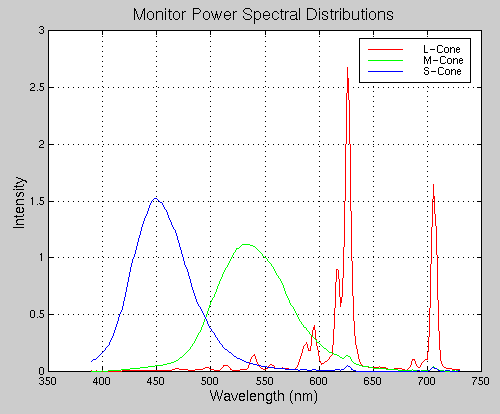
Any light can be broken into a spectral power distribution, which gives the amount of power at each wavelength. As an example, spectral power distribution of the light emitted from each of the red, green and blue guns of a standard computer display is shown in Figure 1.
Figure 1. Spectral Power Distributions of Red, Green and Blue Phosphors on a Typical Computer Display.
Similarly, the spectral sensitivity of any sensor is a function of wavelength. The spectral sensitivities of the L-, M-, and S-cones are shown in Figure 2. The amount, q, that a light stimulates a cone is the sum of the cone sensitivity multiplied by the spectral power of the light at each wavelength:
![]()
where s(w) is the sensitivity of the cone, p(w) is the spectral power distribution of the light source and w is the wavelength. Calculating the sensitivities and power distributions at a discrete set of wavelengths can approximate this integral, so that s(w) and p(w) are replaced by row-vectors S and P respectively.
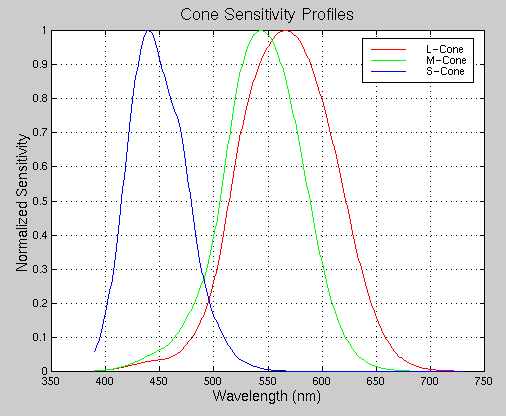
Figure 2. Spectral Sensitivity of Cones.
Using this representation, define
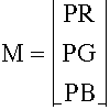
where PR, PG and PB are the full-scale power distributions of the red, green and blue guns on the display. Now if d is a 3x1 vector containing the RGB settings for the monitor, then the spectral power distribution of the monitor is simply
![]()
Similarly, we can define
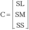
where SL, SM, and SS are the sensitivities of the L-, M-, and S-cones respectively. The "perceived signal" from each of the three cones can be written as a 3x1 vector
Now, combining the above we see that, given RGB values, d, for the display,
![]()
Note that the values in d are linear intensity values. It is assumed that a proper gamma-correction is done prior to display throughout this project.
For simplicity, we will define
![]()
as the transition matrix from RGB values to cone stimulation. For trichromats, T is an invertable 3x3 matrix.
For dichromats, one of the rows of T is zero so that T has a 1-dimensional null-space. Let VL, VM, and VS denote vectors in the null-space of T for dichromats who are missing the L-, M- and S-cones respectively. In reality, the angle between the VL and VM directions is only 10 degrees. The angle between VL and VS directions is 69 degrees, and between VM and VS directions is 66 degrees.
The basic theory, then is that a dichromat missing L-cones will not be able to distinguish two different colours represented on the display if the corresponding d-vectors d1 and d2 differ by a scalar multiple of VL. That is, for such a dichromat,
![]()
This is the theory which explains the differences in vision between a normal tricromat and a dichromat. An assumption which is made throughout this work is that the RGB values are always positive.
2.0 Colour Matching Experiments
The standard colour matching exeriment allows a user to vary the intensities of three primary colours to match a reference light. Assuming that the transition matrix from the primaries to the cone stimulation, z, is invertable, a unique match can always be made by a trichromat. When the reference and match colours are displayed on a computer, both use the same primaries, namely the red, green and blue colour guns of the display. Thus the error in the match is easily measureable, since the RGB values of the match and the RGB values of the reference should be identical.
A dichromat can, in theory, match any light using only two primaries, assuming that the transition matrix from the primaries to the cone stimulation is of rank 2. For the computer matching experiment, the match can be made with two primaries in most cases, with the exception being when a value outside the range [0,1] would be needed for the primaries.
2.1 Experimental Procedure
A colour matching graphical-user-interface (GUI) was designed using Matlab 5.0. The GUI displays a reference colour and the attempt to match as shown in Figure 3. The subject can vary the red, green and blue colour levels in order to create a match.
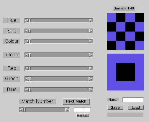
Figure 3. Sample Colour-Matching Graphical User Interface.
Although the concept of colour matching is reasonably simple, in practice it can be quite difficult to adjust colours to make a match. In order to speed up the time to make a match, additional controls were added, allowing the user to vary the hue, saturation and colour value, and the total (red+green+blue) intensity. As controls are adjusted, the GUI updates other controls which depend on the ones adjusted. For example, if the red is increased, the GUI will modify the total intensity control accordingly.
100 matches were performed by a dichromat, and 50 were performed by a trichromat. For each match, the error between the match and the reference colour was calculated as a 3x1 vector. The angle between the error direction and the vectors VL, VM and VS was calculated. Angles were calculated between 0 and 90 degrees so that an angle of 120 degrees between vectors becomes 60 degrees between the vector-lines. The error vectors were then plotted using polar coordinates. The magnitude on the plots is the error vector magnitude, and the phase is the angle between the error vector and the VL, VM or VS direction.
2.2 Results and Discussion
Colour matching is a difficult process! Matches by a dichromat could easily take up to 5 minutes each — so the tolerance of error was increased. The dichromat could typically match without varying the red level, although using the hue and saturation controls was usually quicker.
Figure 4 shows the polar plot of the error vectors for the matches performed by the trichromat. Notice that the angles of the errors are relatively randomly distributed, and the error magnitudes are relatively small.
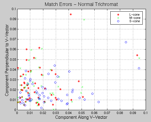
Figure 4. Plot of errors in colour-matching by a normal trichromat with respect to VL, VM and VS directions. The angles of the errors are randomly distributed, and the magnitudes are small.
Figure 5 shows the polar plot of the error vectors for the matches performed by the dichromat, with angles calculated using the VL, VM and VS directions. The angles between vectors are very similar for each of the matches, even though the error magnitudes can be as large as 0.7 on the [0,1]-RGB scale.
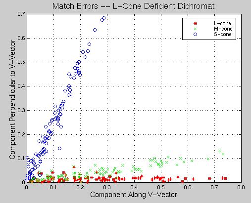
Figure 5. Plot of errors in colour-matching by an L-cone-deficient dichromat. The angles of the errors are along the VL direction, and the magnitudes can be quite large.
Note that the angle between VL and VM is very small. This should not come as a surprise, since the sensitity profiles of the L-cones and the M-cones are very similar. Accordingly the angle between the data and VM is not very large.
3.0 Colour Discrimination Tests
A simple and effective test to identify dichromats is to display different colour patches where the RGB values of the different patches vary along only one of the VL, VM or VS directions. Such a set of patches is shown in Figure 6.
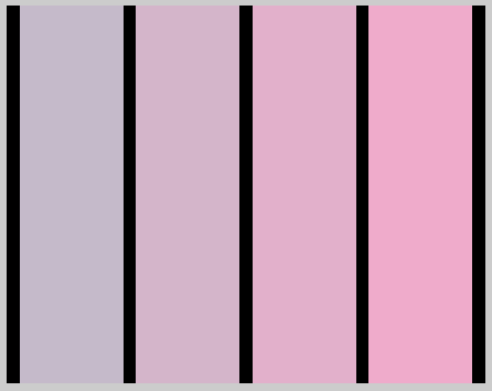
Figure 6. A simple test to see if a subject lacks a particular type of cone. The RGB values of the coloured patches vary only along the VL direction. The patches look identical to a dichromat who lacks L-cones.
3.1 Experimental Procedure
In order to apply a fair test, a Matlab script was written to randomly choose patches as in Figure 6. The subject was asked to tell if the patches were the same or different for each of 50 patch sets. Additionally, half the time, the patches were set to be identical. The test was applied to a normal trichromat and an L-cone deficient dichromat for all three types of cone-deficiency. The result of the test is simply the fraction of correct responses.
3.2 Results and Discussion
The results of the test for the two subjects are shown below:
|
L-Cone Test |
M-Cone Test |
S-Cone Test |
|
|
L-Cone Dichromat |
54% |
64% |
86% |
|
Trichromat |
94% |
94% |
88% |
We would expect the dichromat to score around 50% on the L-Cone test, and higher on the others. Note that the dichromat score is quite low on the M-Cone test as well. This is not surprising, since the directions VL and VM are quite similar, or, equivalently, the L- and M-cone sensitivity profiles are similar.
With a larger sample size and more patch sets in each test, this test might be able to distinguish between L- and M-cone deficient dichromats. While it conclusively identifies the dichromat as a dichromat, it does not tell which cone type is missing.
Samples of simple tests are available at http://www-ise.stanford.edu/class/psych221/99/bah/cbtest.html
4.0 Conclusion
In this project, two computer-based methods of classifying dichromats were tested. A colour-matching method accurately identifies the type of cones which are missing in a dichromat, but is a lengthy test. A simpler test with different colour patches can identify dichromats, but does not necessarily tell which cones the dichromat is missing.